Lumbar traction table

a technology of lumbar traction and treatment table, which is applied in the field of chiropractic treatment table, can solve problems such as the movement of the handle, and achieve the effect of enhancing longitudinal traction

Active Publication Date: 2007-10-23
DANZEY WILLIAM P
View PDF12 Cites 17 Cited by
  • Summary
  • Abstract
  • Description
  • Claims
  • Application Information

AI Technical Summary

Benefits of technology

[0016]The present invention provides several advantages for spinal treatment afforded by a chiropractic table which includes the present invention's features. This improved chiropractic table automatically produces a progressive amount of longitudinal traction as flexion is applied by the downward pivotal movement of the pelvic support section. Differential amounts of longitudinal traction may be selected by optional pivotal location of the traction bar member at the time of treatment. Moreover, the present invention, when assisted by gravity to produce enhanced longitudinal traction, allows the practitioner to produce a degree of longitudinal traction not possible with existing traction tables and by connecting the traction handle to the non-sliding lower pelvic section of the pelvic support section, the traction handle does not move away from the practitioner during flexion.
[0017]This invention is thus directed to a flexion-traction type lumbar traction table for supporting and treating a patient including a base supporting a stationary head-thoracic support and a pivotally movable pelvic support section positioned in spaced end-to-end relation to the head-thoracic support section. Upper and lower pelvic sections form the pelvic support section and are connected together for sliding longitudinal translation of the upper pelvic section on the lower pelvic section. A proximal end of the lower pelvic section is connected for pivotal movement about a horizontal transverse flexion axis between a horizontal first position and a downwardly inclined second position. An axial traction member is pivotally connected between the upper pelvic section adjacent to a distal end thereof and the frame just beneath the flexion axis wherein said upper pelvic section is automatically slidably translated further from said proximal end of the lower pelvic section as the pelvic support section is manually pivoted downwardly for enhanced longitudinal traction.
[0018]It is therefore an object of this invention to provide a flexion-type lumbar traction table which enhances and extends the amount of flexion traction that may be introduced to the patient by the practitioner during chiropractic treatment.
[0019]It is still another object of this invention to provide a selectable degree of enhanced flexion traction afforded by a lumbar traction table.
[0020]Still another object of this invention is to incorporate the present invention into flexion-distraction spinal traction tables which introduce both flexion-distraction and lateral-distraction separately or together and for producing enhanced traction extension of the spine during either or both of these treatment procedures.
[0021]Yet another object of this invention is to provide a traction handle for pivotal downward flexion-distraction patient movement which does not move away from the practitioner with increased downward pivotal movement.

Problems solved by technology

Also, with the Cox design, the traction handle moves away from the practitioner which would be impractical during lumbar flexion distraction as the practitioner's hands are already significantly separated.

Method used


Image

  • Lumbar traction table
  • Lumbar traction table
  • Lumbar traction table

Examples


Embodiment Construction

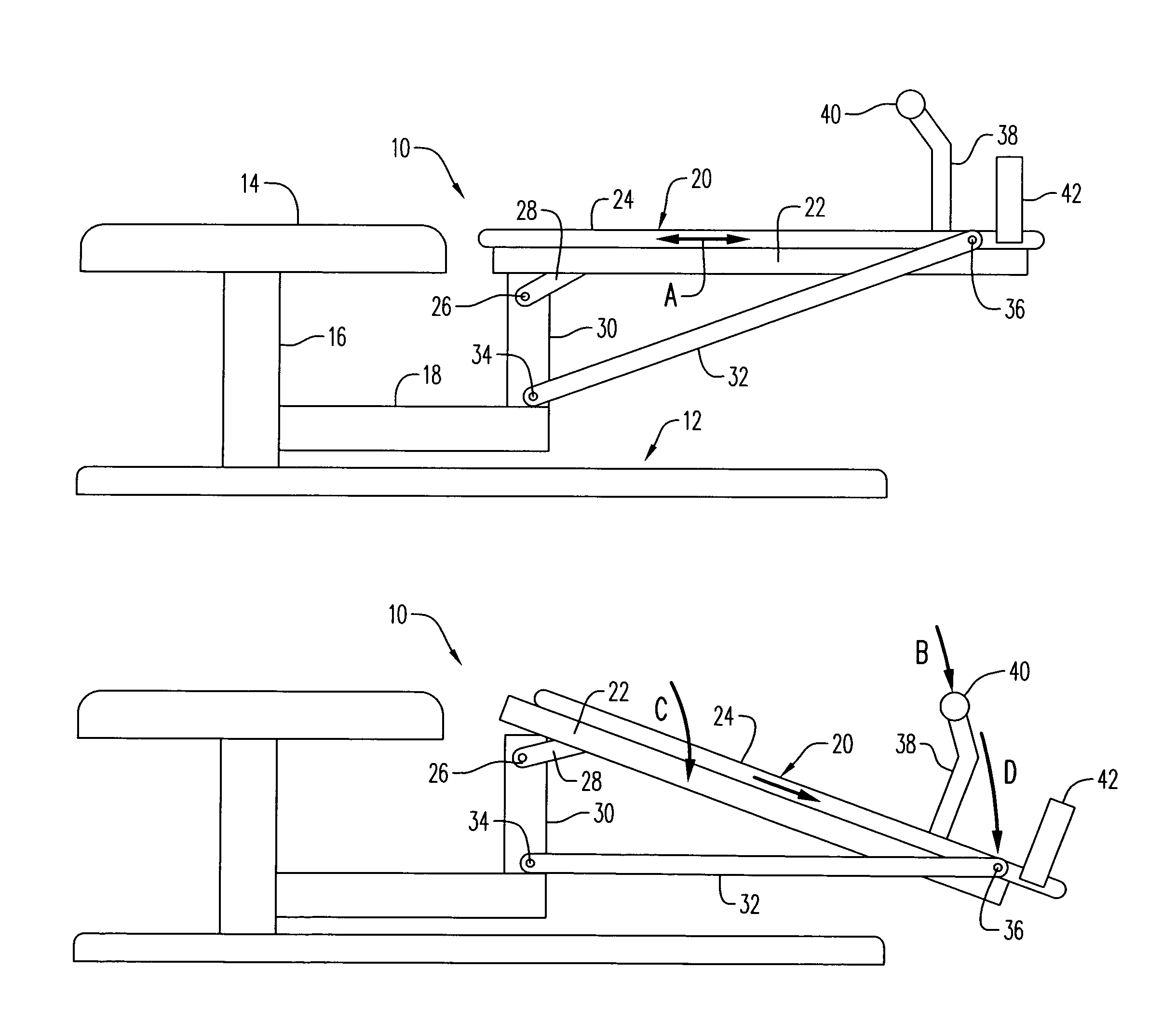
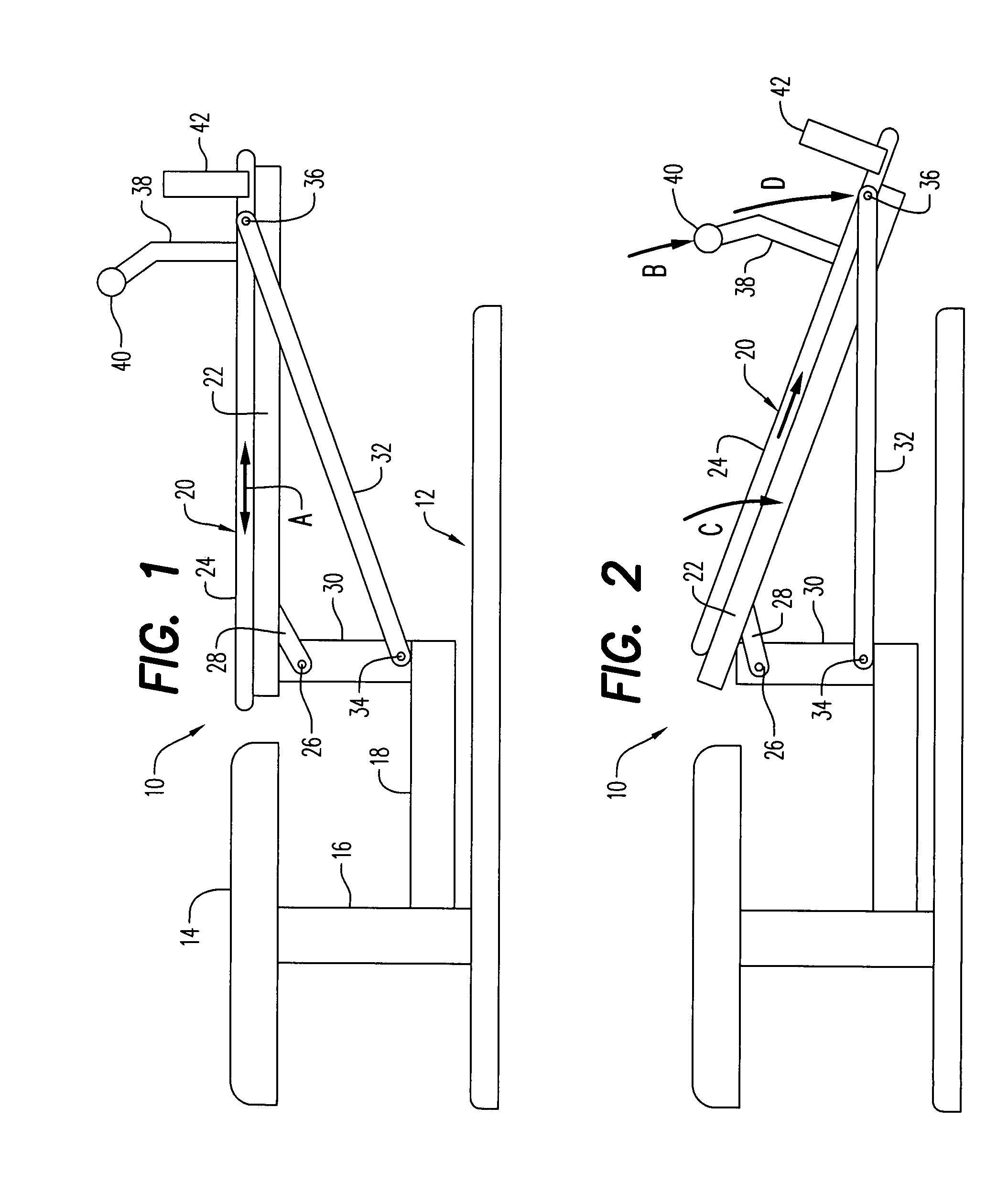
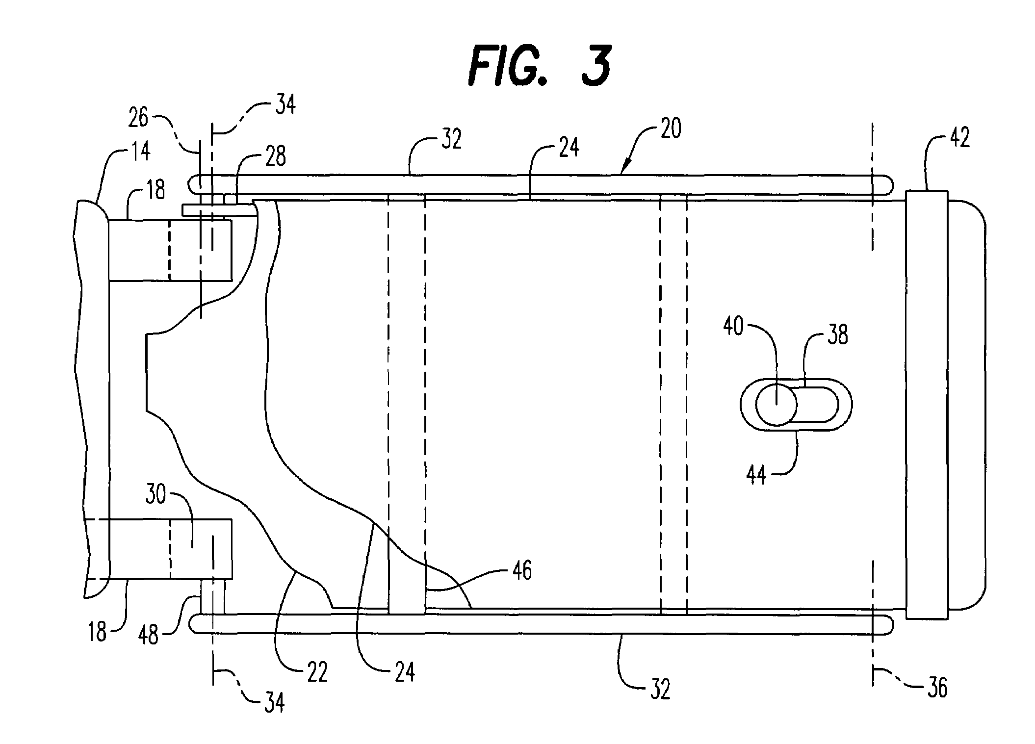
[0028]Referring now to the drawings, and firstly to FIGS. 1 to 3, one embodiment of a flexion-traction type lumbar traction table embodying aspects of the invention is there shown generally at numeral 10. This traction table 10 includes a frame 12 supportable atop a level floor surface and which includes an upright support 16 having a horizontally disposed stationary head-thoracic support section 14 connected thereatop. Two spaced longitudinally extending frame members 18 as best seen in FIG. 3 extend from the upright support 16 beyond the proximal end of the frame head-thoracic support section 14. An upwardly extending frame member 30 is supportively connected at a lower end thereof to the end of each horizontal frame member 18.

[0029]A pelvic support section 20 includes a lower pelvic section 22 and an upper pelvic section 24 which is slidably engaged for longitudinal movement only in the direction of arrow A to and atop the lower pelvic section 22. The lower pelvic section 22 is p...


PUM


Abstract

A flexion-traction type lumbar traction table for treating a patient including a base supporting a stationary head-thoracic support and a pivotally movable pelvic support section positioned end-to-end with the head-thoracic support section. Upper and lower pelvic sections form the pelvic support section and are connected together for sliding longitudinal translation of the upper pelvic section on the lower pelvic section. A proximal end of the lower pelvic section is connected for pivotal movement about a horizontal transverse flexion axis between a horizontal first position and a downwardly inclined second position. An axial traction member is pivotally connected between the upper pelvic section adjacent to a distal end thereof and the frame just beneath the flexion axis wherein said upper pelvic section is automatically slidably translated further from said proximal end of the lower pelvic section as the pelvic support section is manually pivoted downwardly for enhanced longitudinal traction.

Description

CROSS-REFERENCE TO RELATED APPLICATIONS[0001]Not applicableSTATEMENT REGARDING FEDERALLY SPONSORED RESEARCH OR DEVELOPMENT[0002]Not applicableINCORPORATION-BY-REFERENCE OF MATERIAL SUBMITTED ON A COMPACT DISC[0003]Not applicableBACKGROUND OF THE INVENTION[0004]1. Field of the Invention[0005]This invention relates generally to chiropractic treatment tables of the type for generally horizontally supporting a patient in a face-down position, and more particularly to such a table with improved axial traction during flexion-distraction and lateral-distraction, or the combination of both.[0006]2. Description of Related Art[0007]Currently, lumbar flexion-distraction tables used by chiropractors produce a very slight longitudinal traction by pivotal displacement of the pelvic support section that occurs during flexion. The downwardly pivotal movement of the pelvic support section about a transverse horizontal axis positioned adjacent the head-thoracic support section of the table effects th...

Claims


Application Information

Patent Timeline
Patent Type & Authority Patents(United States)
IPC IPC(8): A61H1/02A61F5/00
CPCA61H1/0218A61H1/0222A61H2203/0468A61H2201/1642
Inventor DANZEY, WILLIAM P.
Owner DANZEY WILLIAM P
Why Eureka
Try Eureka