Container for use with flexible bags

Inactive Publication Date: 2007-10-23
JOLLY DAVID M +1
View PDF15 Cites 17 Cited by
  • Summary
  • Abstract
  • Description
  • Claims
  • Application Information

AI Technical Summary

Benefits of technology

[0008]Using the container embodying the present invention will permit a user to remove air from the container as a flexible bag is being placed into the container whereby the bag will be easily placed into the container and wi

Problems solved by technology

Typically, in residential and commercial trash collection, however, it has been observed that the plastic liner due to its flexible nature tends to cling to the inside wall of the trash receptacle, and as the trash liner is progressively filled with refuse material, the liner further clings to the trash receptacle wall and ultimately substantially fills the space defined by the receptacle wall.
In this manner, trash can liners can become stuck within a trash can by the vacuum seal created when the trash can liner contacts the sidewalls of the trash can.
When this happens it can be difficult, particularly for weak and infirm individuals, to physically pull the trash can liner out of the trash can.
In some cases, pulling a bag against such a vacuum may even tear the bag.
An additional problem o

Method used


Image

  • Container for use with flexible bags
  • Container for use with flexible bags

Examples


Example

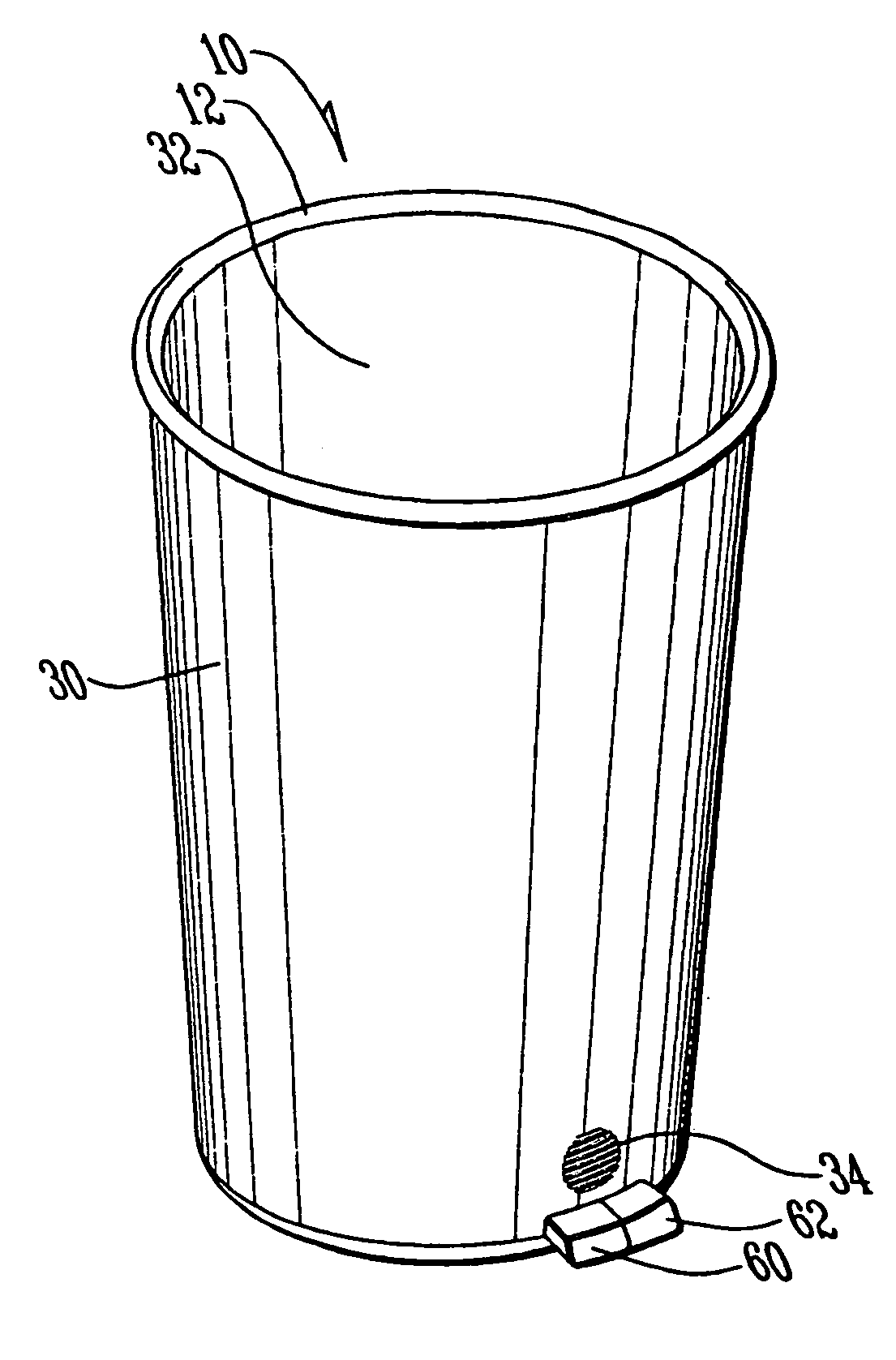
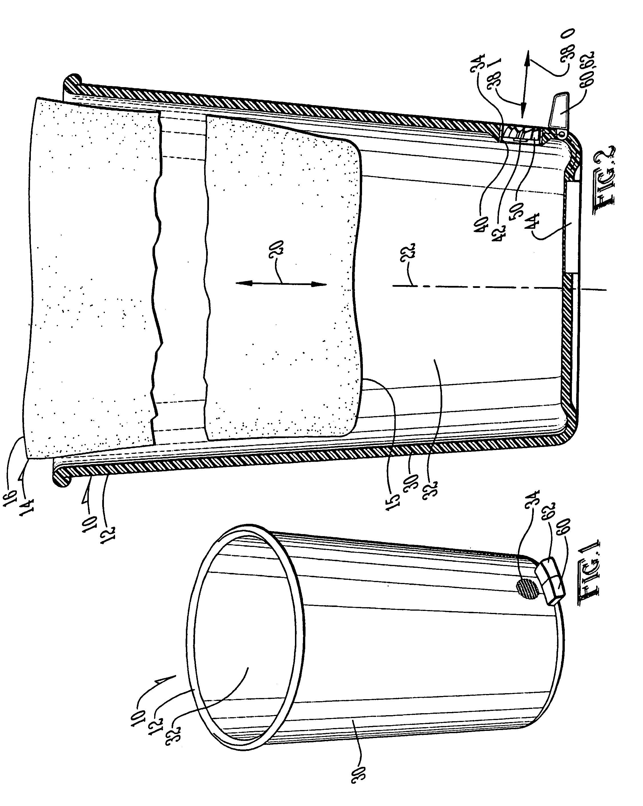
[0013]FIG. 1 shows a container 10 including a shell 12 which is adapted to accommodate a flexible bag, such as a flexible trash bag 14, or the like. Shell 12 includes a first end 14 which is a bottom end when shell 12 is in use. As can be understood from FIG. 2, first end 14 is closed. A second end 16 is a top end when shell 12 is in use and is open so the bag can be placed into the container and removed as indicated by double-headed arrow 20. A longitudinal axis 22 extends between first end 14 and second end 16 and the bag moves in the direction of the longitudinal axis when being placed into the container and being removed from the container.

[0014]A wall 30 connects first end 14 to second end 16 and is preferably cylindrical, but could be other shapes as well without departing from the scope of this disclosure. Wall 30 and first end 14 define an interior volume 32 of shell 12. As can be understood from FIG. 2, the flexible bag is accommodated in interior volume 32. A vent port 34 ...


PUM


Abstract

A container includes a fan that is reversible so air can be removed from the container as a flexible bag is placed into the container and ambient air can be forced into the container when the flexible bag is being removed from the container. This will facilitate placement and removal of a flexible bag in and from the container.

Description

BACKGROUND OF THE INVENTION[0001]1. Field of the Invention[0002]The present invention relates to the general art of containers, and to the particular field of trash containers.[0003]2. Background of the Invention[0004]Conventionally, trash or other refuse material is collected and bagged in a flexible plastic liner placed within a rigid, upstanding receptacle. Typically, in residential and commercial trash collection, however, it has been observed that the plastic liner due to its flexible nature tends to cling to the inside wall of the trash receptacle, and as the trash liner is progressively filled with refuse material, the liner further clings to the trash receptacle wall and ultimately substantially fills the space defined by the receptacle wall. During this process, any air present between the liner and the receptacle wall slowly leaks out, and when the trash-filled liner occupies the interior space of the receptacle, a vacuum is created between the trash liner and the receptac...

Claims


Application Information

Patent Timeline
IPC IPC(8): H02P3/20
CPCB65F1/06B65F1/068B65F2210/179
Inventor JOLLY, DAVID M.JOLLEY, GLYNDEL
Owner JOLLY DAVID M
Why Eureka
Try Eureka