Switching device for power distribution

a technology of switching device and power distribution, which is applied in emergency protective arrangements, non-enclosed substations, substations, etc., can solve problems such as reliability reduction, and achieve the effect of improving reliability

Inactive Publication Date: 2007-10-23
HITACHI ELECTRIC SYSTKK
View PDF6 Cites 16 Cited by
  • Summary
  • Abstract
  • Description
  • Claims
  • Application Information

AI Technical Summary

Benefits of technology

[0007]Accordingly, it is an object of the present invention to provide a switching device for power distribution, wherein the entire load side-area including the circuit breaker can be protected against the grounding, whereby the protection region can be widened, leading to an enhancement in reliability.
[0010]According to the present invention, the zero-phase current transformer is disposed at the power source side-portion of the circuit breaker. Therefore, the entire load side-area including the circuit breaker can be protected against the grounding and hence, the protection region can be widened, leading to an enhancement in reliability.

Problems solved by technology

For this reason, the prior art switching device raises such a problem that it is impossible to detect the grounding of a breaker area including the circuit breaker located at the power source side-portion of the zero-phase current transformer, resulting in a reduction in reliability.

Method used


Image

  • Switching device for power distribution
  • Switching device for power distribution
  • Switching device for power distribution

Examples


embodiment 1

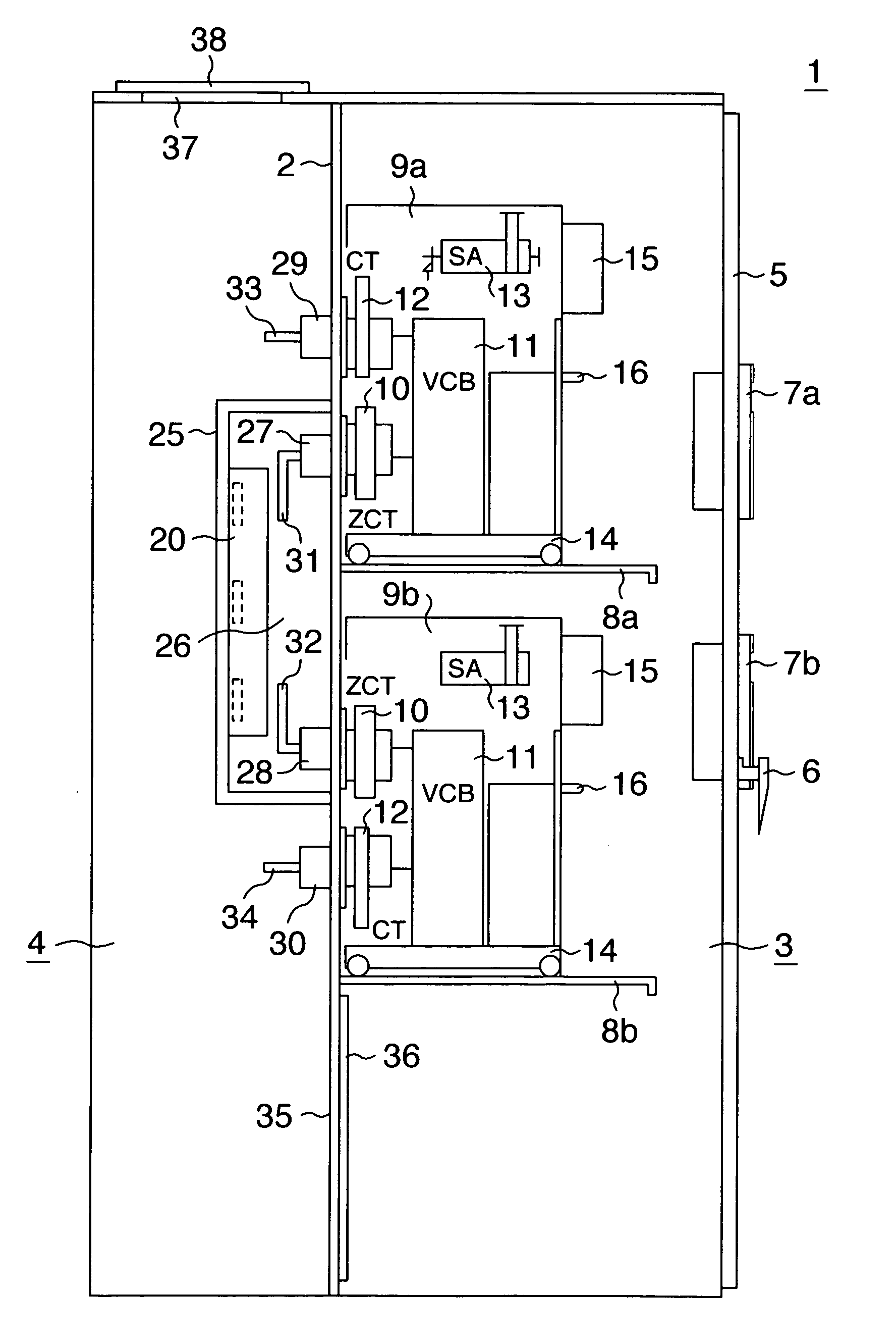
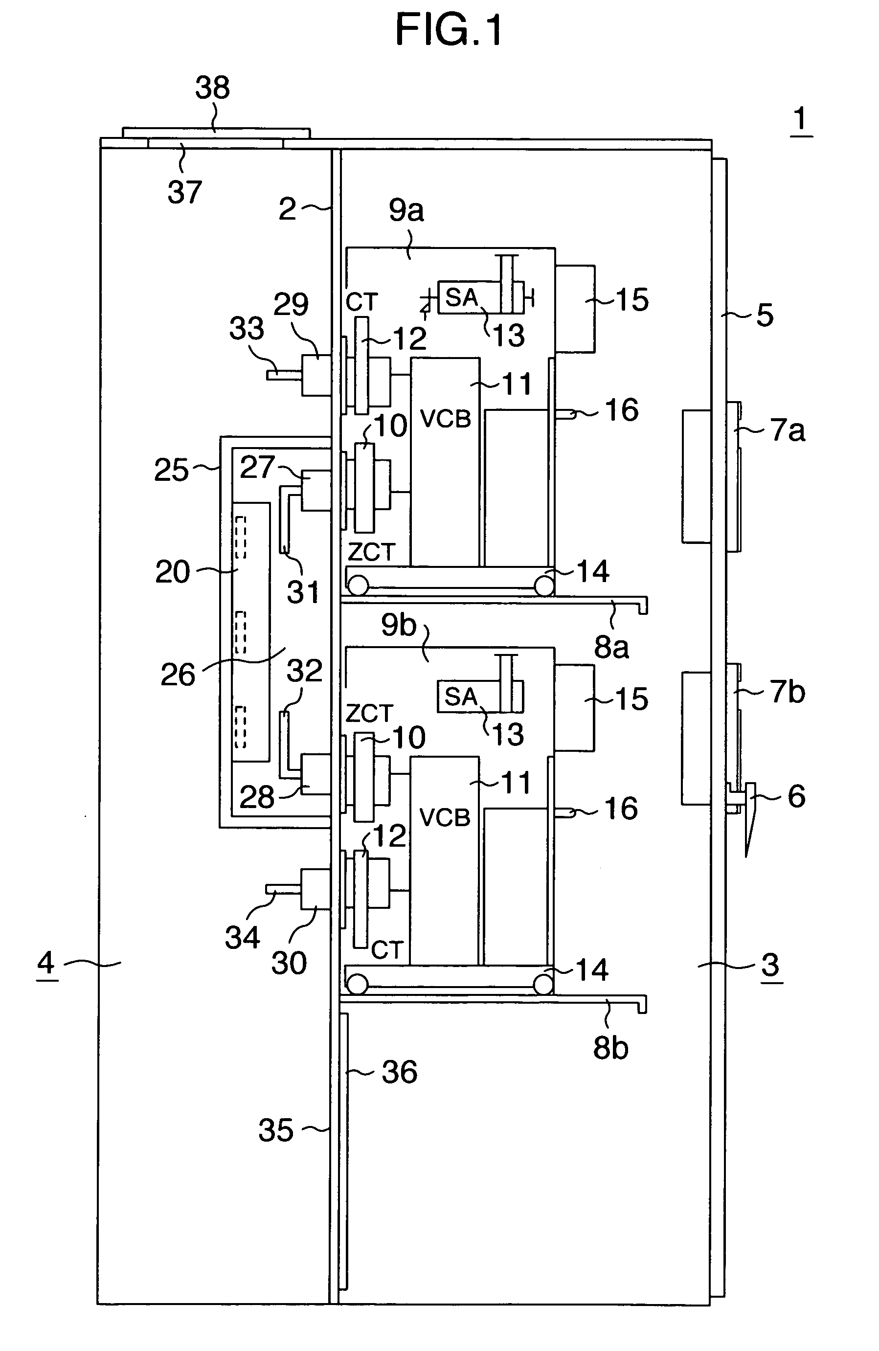
[0024]FIG. 1 shows one embodiment of the present invention. FIG. 1 is a side view showing the entire arrangement of an example in which two switching units for power distribution are stacked vertically one on another.

[0025]Referring to FIG. 1, a power receiving / distributing board 1 is partitioned by a partition plate 2 into a right section and a left section as shown in FIG. 1, wherein a front surface side of the right section defines a circuit breaker chamber 3, and a back surface side of the left section defines a cable chamber 4. A door 5 having a handle 6 is mounted on a front surface of the power receiving / distributing board 1. Two grounding (over-current) protection relays 7a and 7b are mounted to the door 5.

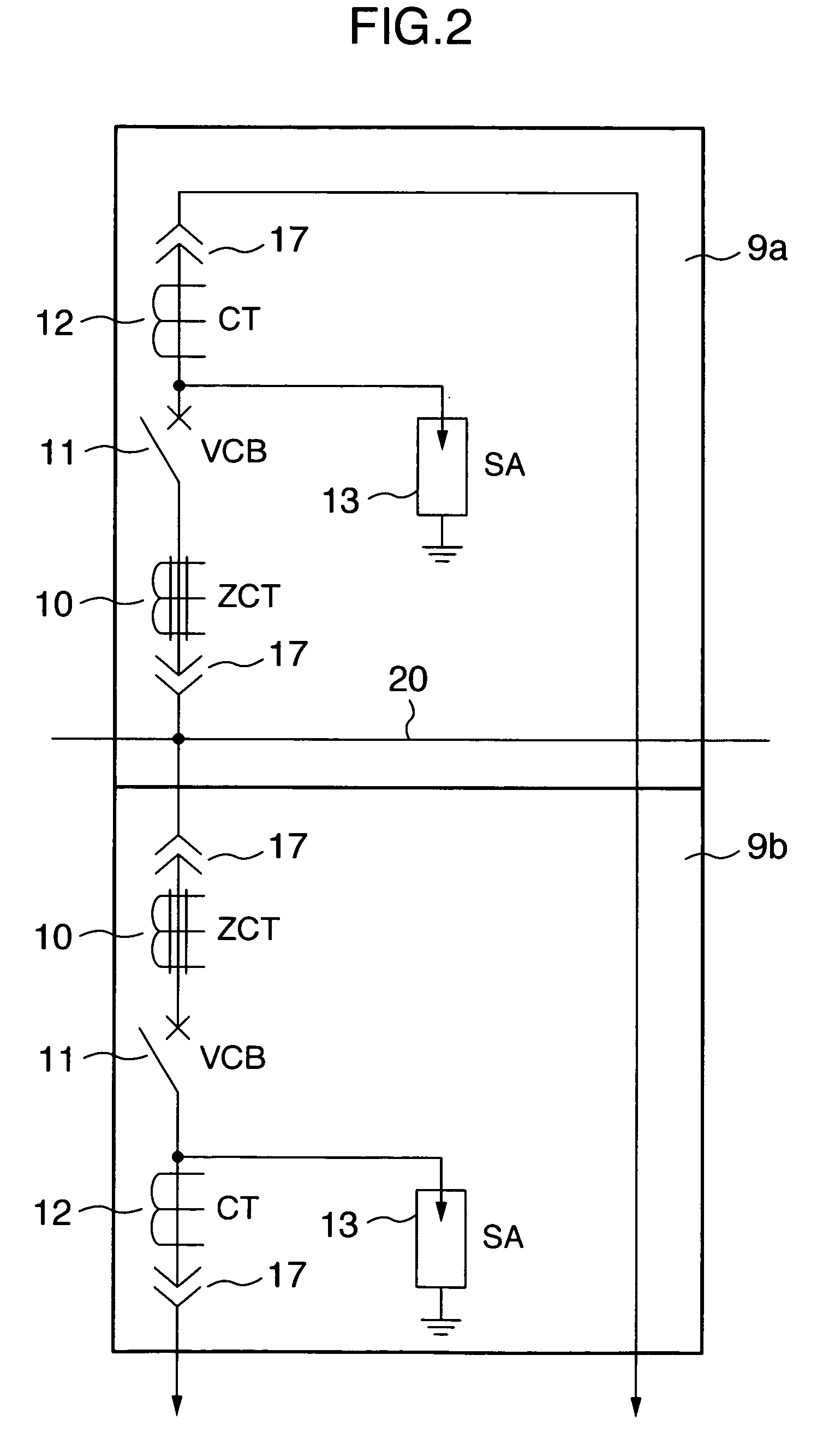
[0026]Two support plates 8a and 8b fixed to the partition plate 2 are disposed in the circuit breaker chamber 3. The two switching units 9a and 9b for power distribution are placed on the support plates 8a and 8b. The switching unit 9 for power distribution comprises a zer...

embodiment 2

[0047]Another embodiment of the present invention is shown in FIG. 9. In the embodiment shown in FIG. 9, a zero-phase current transformer 10, a vacuum circuit breaker 11 and a current transformer 12 are shown, in a schematic connection view, as being disposed in a dispersed manner in a power receiving / distributing board 1 rather than being formed as a unit.

[0048]In FIG. 9, connecting fitments 17 are disposed at a power source side-portion and a load side-portion of the vacuum circuit breaker 11, so that only the circuit breaker 11 may be connected to and disconnected from a power source side-conductor 20 and a load side-conductor. Even if the zero-phase current transformer 10, the vacuum circuit breaker 11 and the current transformer 12 are disposed in the dispersed manner as described above, an advantageous effect similar to that in the embodiment 1 is obtained.

embodiment 3

[0049]A further embodiment of the present invention is shown in FIG. 10. In the embodiment shown in FIG. 10, a circuit breaker chamber 3 in a power receiving / distributing board 1 is formed so that it can be slid toward a front surface, thereby ensuring an inspecting space 50. The sliding of the circuit breaker chamber 3 can be achieved, for example, by a guide rail. To make access into the inspecting space 50, the circuit breaker chamber 3 is pulled out, thereby utilizing an inspecting aperture 51 formed in a ceiling plate and an inspecting aperture 35 provided in a lower portion of a partition plate 2.

[0050]In a case where a plurality of power receiving / distributing boards are disposed in a row arrangement, an inspecting space (an inspecting passage) 50 as shown in FIG. 11 is formed. The inspecting space 50 is formed over the entire row of the boards, but only one of the power receiving / distributing boards, which is required to be inspected, can be pulled out to form an inspecting ...


PUM


Abstract

An object of the present invention is to provide a switching device for power distribution, wherein the entire load side-area including a circuit breaker can be protected against the grounding, whereby the protection region can be widened, leading to an enhancement in reliability. A circuit breaker, a current transformer and a zero-phase current transformer disposed in series are constructed as a unit, mounted on a carriage and accommodated in a power-receiving / distributing board. The switching unit for power distribution is constructed for connection to and for disconnection from a power source side-conductor and a load side-conductor. The zero-phase current transformer is disposed at a power source side-portion of the circuit breaker.

Description

BACKGROUND OF THE INVENTION[0001]1. Field of the Invention[0002]The present invention relates to a switching device for power distribution constructed in such a manner that a circuit breaker, a current transformer and a zero-phase current transformer are disposed in series.[0003]2. Description of the Related Art[0004]As well known, a switching device for power distribution is constructed in such a manner that a circuit breaker, a current transformer (a current transformer for a meter) and a zero-phase current transformer are disposed in series. A vacuum circuit breaker is used as the circuit breaker, and in usual, a surge absorber is mounted.[0005]Such a switching device for power distribution is constructed as a unit, mounted on a carriage and accommodated in a power-receiving / distributing board. The switching device is formed so that it can be connected to and disconnected from a power source side-conductor and a load side-conductor by moving the carriage or by sliding the unit on...

Claims


Application Information

Patent Timeline
Patent Type & Authority Patents(United States)
IPC IPC(8): H02B5/00
CPCH02B11/167H02B11/02H02B1/32H02B1/36
Inventor MASUHARA, HIDEKISIBATA, YOUZOUKAWAMURA, YASUHIRO
Owner HITACHI ELECTRIC SYSTKK
Why Eureka
Try Eureka