System for monitoring managed server health

a server health and server technology, applied in the field of monitoring the health of managed servers, can solve problems such as failure to restart servers

Inactive Publication Date: 2007-10-23
ORACLE INT CORP
View PDF31 Cites 25 Cited by
  • Summary
  • Abstract
  • Description
  • Claims
  • Application Information

AI Technical Summary

Benefits of technology

This patent describes how network devices can be controlled through various means such as settings in the device itself or via an administration server. These controls can include changing configurations, accessing remote management tools, and even being remotely commanded by an administrator. To ensure secure communication, both the device and the server should verify their identity during these interactions. Overall, this technology allows for more efficient and flexible ways to manage networks from different locations.

Problems solved by technology

The technical problem addressed in this patent is how to monitor and improve the health of servers in a distributed network, ensuring proper functioning and preventing failures from impacting other servers and resources.

Method used


Image

  • System for monitoring managed server health
  • System for monitoring managed server health
  • System for monitoring managed server health

Examples


Embodiment Construction

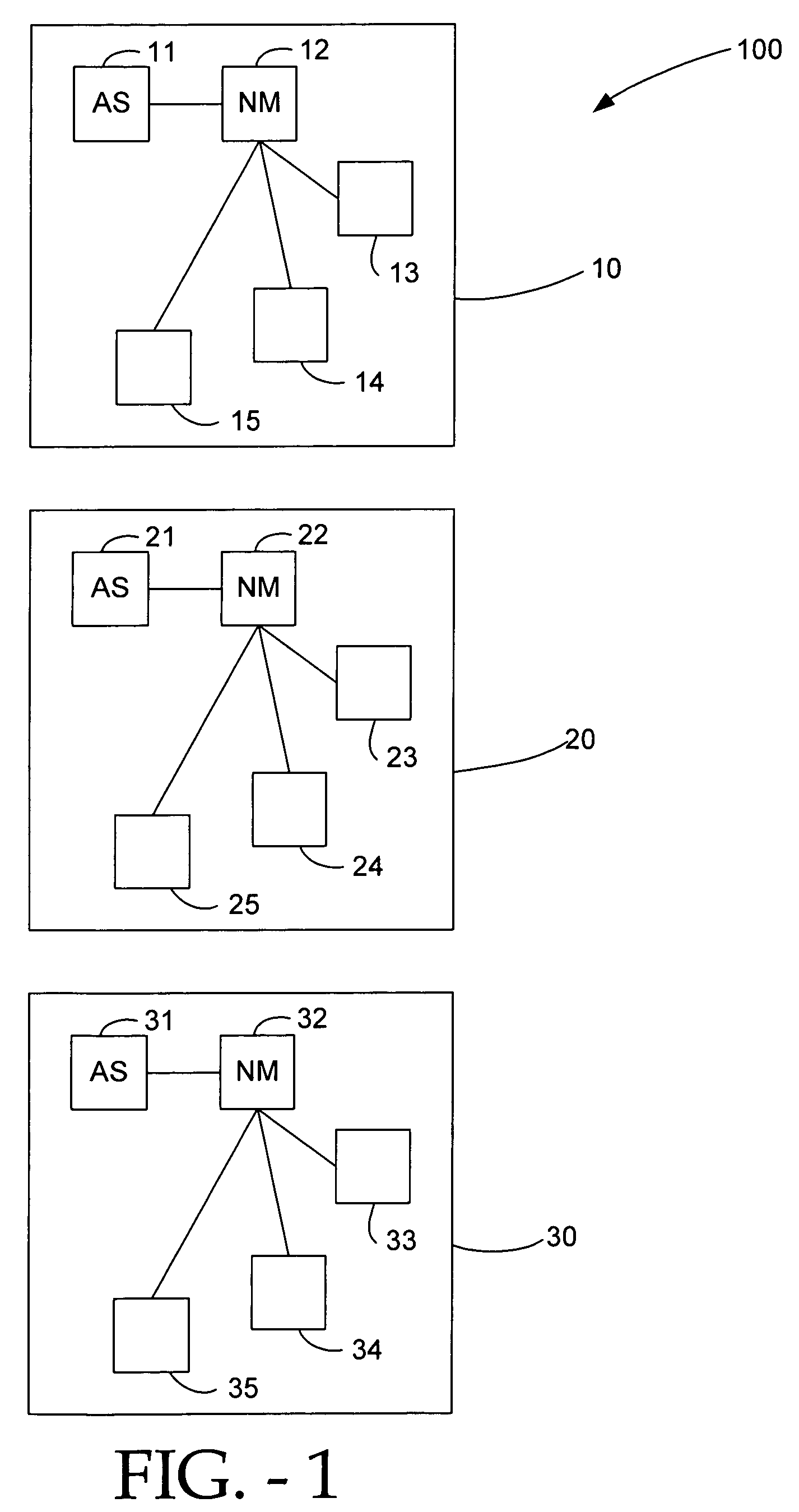
[0021]A self health monitoring system may be composed of several nodes. A node may be a single physical machine or take some other form. In one embodiment of the present invention, each node has a Node Manager (NM), an Administration Server (AS), and several other managed servers or server instances. The AS and NM may send and transmit messages to each other. The NM may also send and transmit messages with the other servers located on the node.

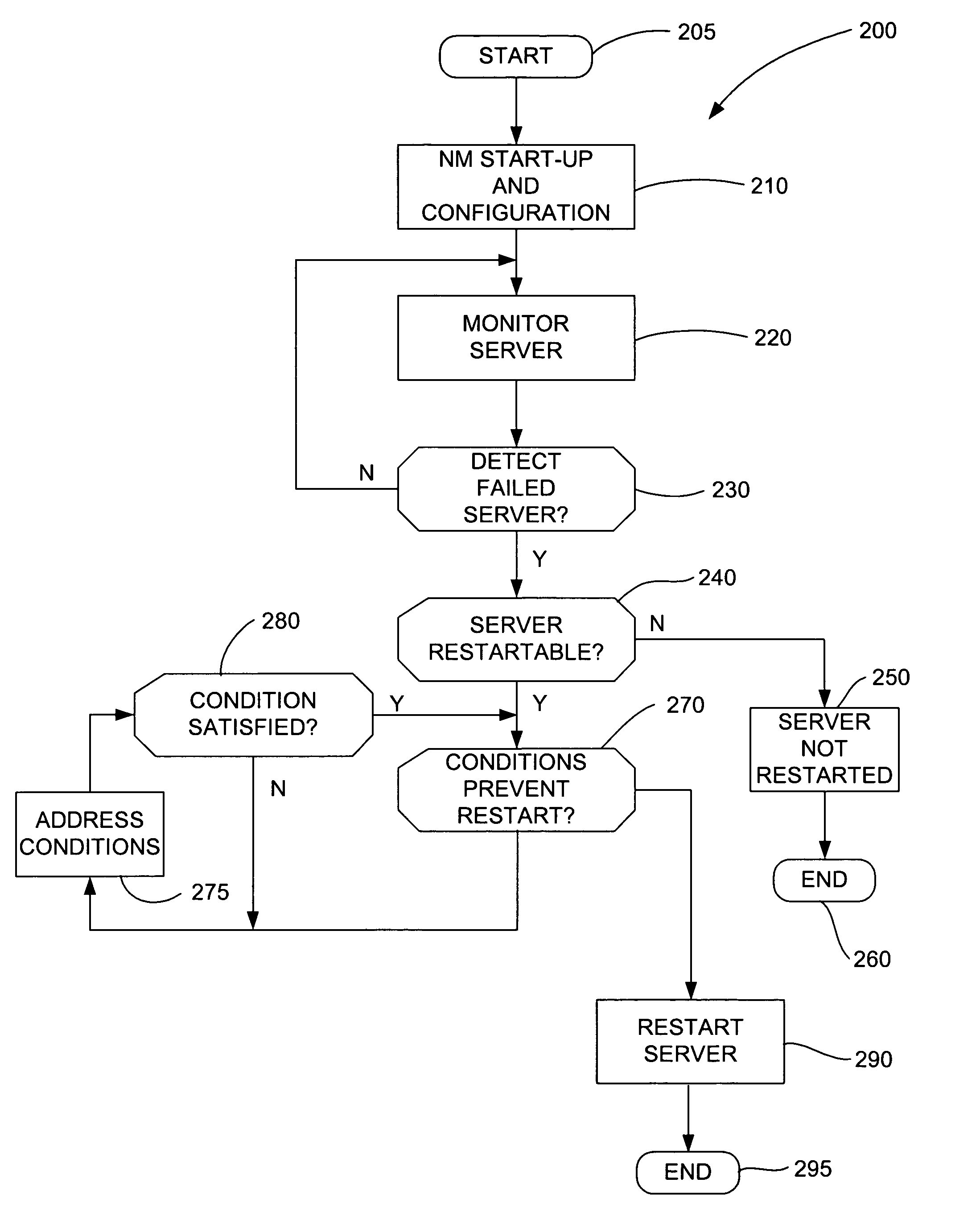
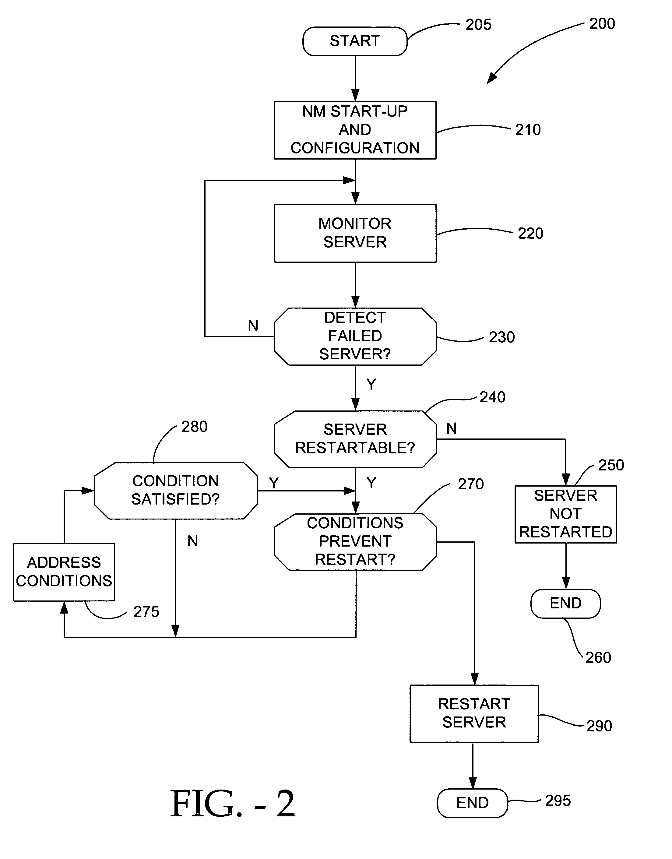
[0022]In one embodiment, the NM performs two primary functions. First, the NM automatically detects and restarts failed servers. The NM continually monitors servers running on the local machine. Upon detecting a server has failed, the NM will automatically restart the failed server. The server restart may occur as soon as the NM detects the server failure. Secondly, the NM periodically monitors and restarts failed or degenerate servers. The NM will periodically monitor servers running on the local machine. When the NM detects that a server is ...


PUM


Abstract

A Node Manager monitors the status of multiple servers. The Node Manager detects server failures, periodically monitors server health status, and performs server maintenance. When the Node Manager detects a server failure, it determines whether or not the server should be restarted. While periodically monitoring servers, the Node Manager may determine how often to trigger a health check, how long to wait for a response, and how to proceed if the server is deemed failed. The Node Manager may be controlled by an Administrative Server directly or by an external administrative agent. An administrative agent may control the Node Manager by interfacing with the Administrative Server. The Node Manager and AS may authenticate each other and encode their communications to each other for increased security.

Description


Claims


Application Information

Patent Timeline
Owner ORACLE INT CORP
Why Eureka
Try Eureka