Double deck elevator

a double-decked elevator technology, applied in the direction of elevators, building lifts, transportation and packaging, etc., can solve the problems of noisy noise and disturb quietness, and achieve the effect of reducing air turbulence noise, improving quietness and comfort in the cages

Inactive Publication Date: 2007-10-30
KK TOSHIBA
View PDF15 Cites 2 Cited by
  • Summary
  • Abstract
  • Description
  • Claims
  • Application Information

AI Technical Summary

Benefits of technology

[0012]It is therefore a general object of the present invention to provide a double deck elevator that can reduce air turbulence noise and improve quietness and comfortableness in the cages.

Problems solved by technology

The air turbulence results in big noise that disturbs quietness and comfortableness in the upper and lower cages 6, 7.

Method used


Image

  • Double deck elevator
  • Double deck elevator
  • Double deck elevator

Examples


Embodiment Construction

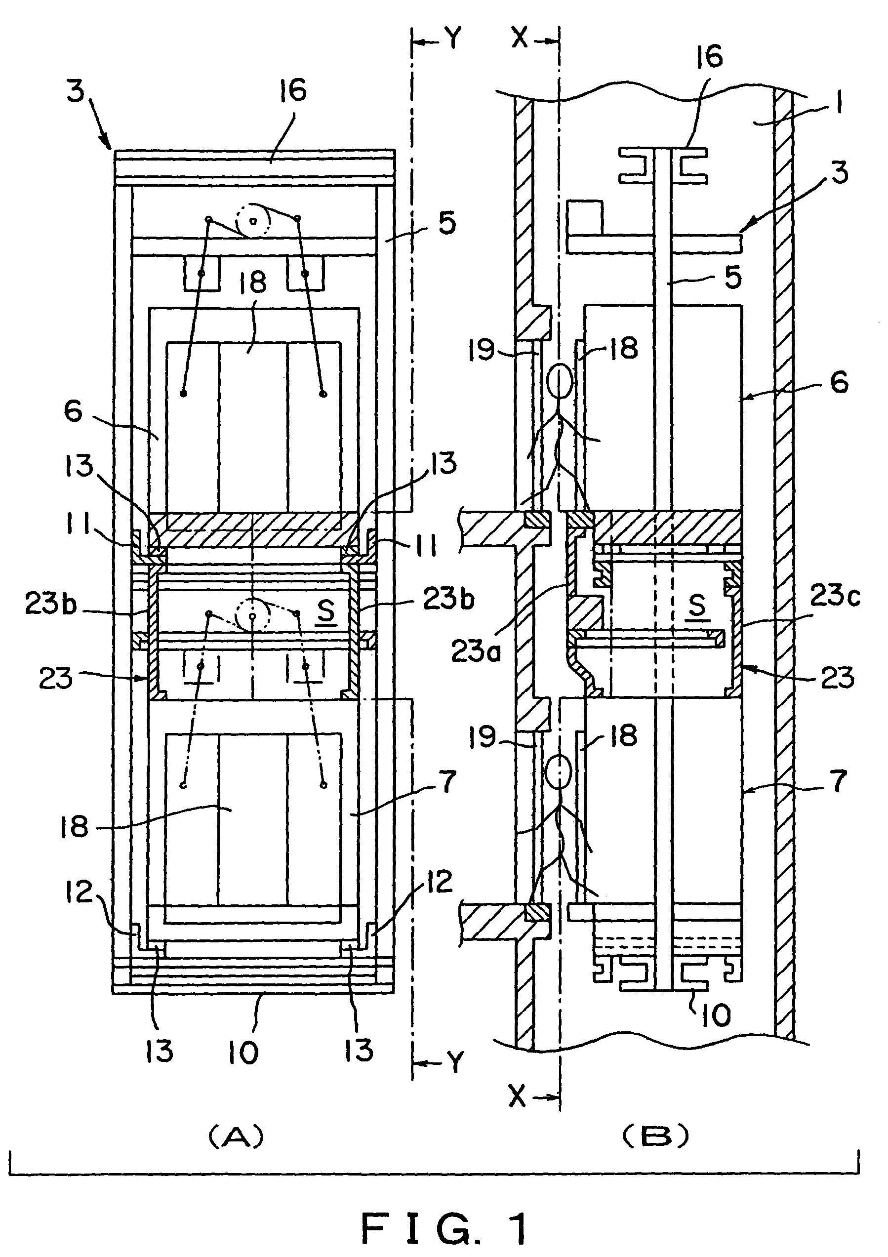
[0048]Referring to the attached drawings, in FIGS. 1A and 1B, there is shown a double deck elevator comprising an upper cage 6 and a lower cage 7 vertically movable together in a hoistway 1.

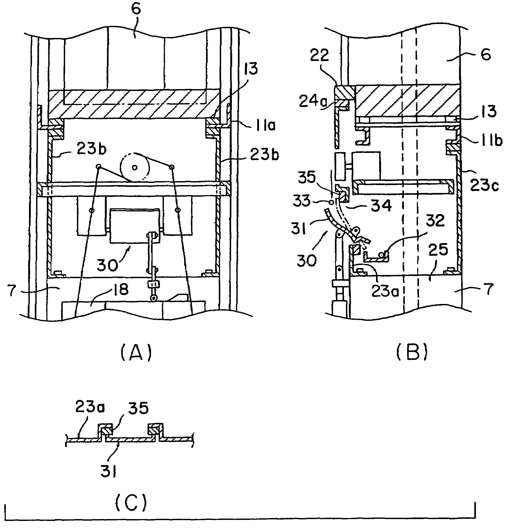
[0049]A space “S” existing between the upper cage 6 and the lower cage 7 is covered by the covers 23 including a door-side cover 23a, two lateral-side covers 23b and a backside cover 23c. That is, the space “S” is covered at a door-side, two lateral-sides and backside respectively.

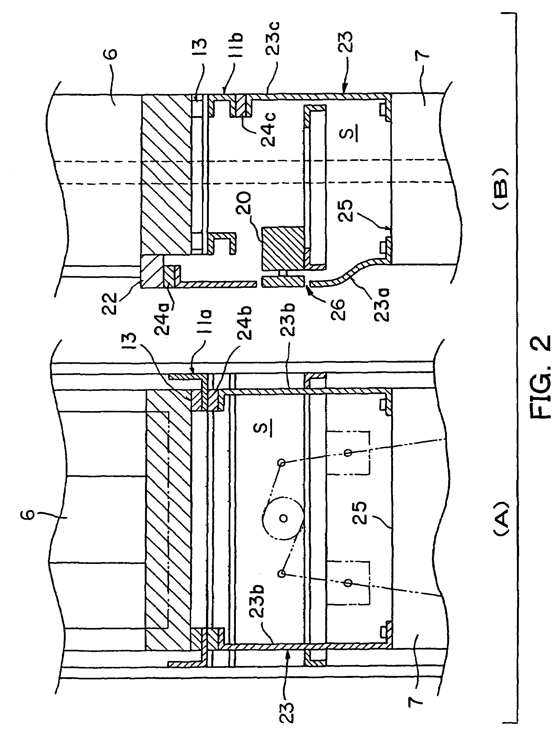
[0050]As shown in FIGS. 2A and 2B, the door-side cover 23a is formed so that its bottom half curves into the space “S” to absorb horizontal position difference between a sill 22 of the upper cage 6 and a ceiling 25 of the lower cage 7. And, all of these covers have smooth flat outer surfaces that are connected to the outer side surfaces of the upper and lower cages 6, 7 each other without steps. And the door-side cover 23a is provided with an opening 26 into which the front portion of a door-driving unit 20 is inserted....


PUM


Abstract

A double deck elevator comprising an upper cage and a lower cage vertically movable together in a hositway, wherein a space between the upper cage and the lower cage is covered by covers. The covers guide airflow flowing around the space to reduce air turbulence noise, and consequently the quietness and comfortableness in the cages is improved.

Description

[0001]This is a divisional of application Ser. No. 09 / 795,357, filed Mar. 1, 2001, now U.S. Pat. No. 6,615,952 which is incorporated herein by reference.BACKGROUND OF THE INVENTION[0002]1. Field of the Invention[0003]The present invention relates to a double deck elevator comprising an upper cage and a lower cage vertically movable together in a hoistway, and more particularly to a double deck elevator wherein a space existing between the upper cage and the lower cage is covered with covers for reducing air turbulence noise to improve quietness and comfortableness in the cages.[0004]2. Description of the Related Art[0005]In conventional double deck elevators shown in FIGS. 23, 24 and 25, a hoistway 1 is provided with a pair of guide rails 2 vertically extending along the inner walls of the hoistway 1 respectively, and a cage assembly 3 hoisted by a main rope 4 is arranged between the guide rails 2 to move vertically guided by the guide rails 2.[0006]The cage assembly 3 comprises a c...

Claims


Application Information

Patent Timeline
Patent Type & Authority Patents(United States)
IPC IPC(8): B66B9/00B66B11/02B66B7/00B66B1/14B66B1/24
CPCB66B11/0095B66B11/0226B66B11/0213B66B9/00
Inventor ITOH, HIROAKIKOHARA, HIDEYAHAYAKAWA, MASAHIRYOKOI, GEN
Owner KK TOSHIBA
Why Eureka
Try Eureka