
Ceiling suspension structure

a technology of suspension structure and support structure, which is applied in the direction of building scaffolds, machine supports, other domestic objects, etc., can solve the problems of system installation that is often difficult or inconvenient, and achieve the effect of facilitating alignment with the overhead support structure and facilitating installation

Active Publication Date: 2007-10-30
SULLIVAN BAZINET BONGIO
View PDF15 Cites 39 Cited by
  • Summary
  • Abstract
  • Description
  • Claims
  • Application Information

AI Technical Summary

Benefits of technology

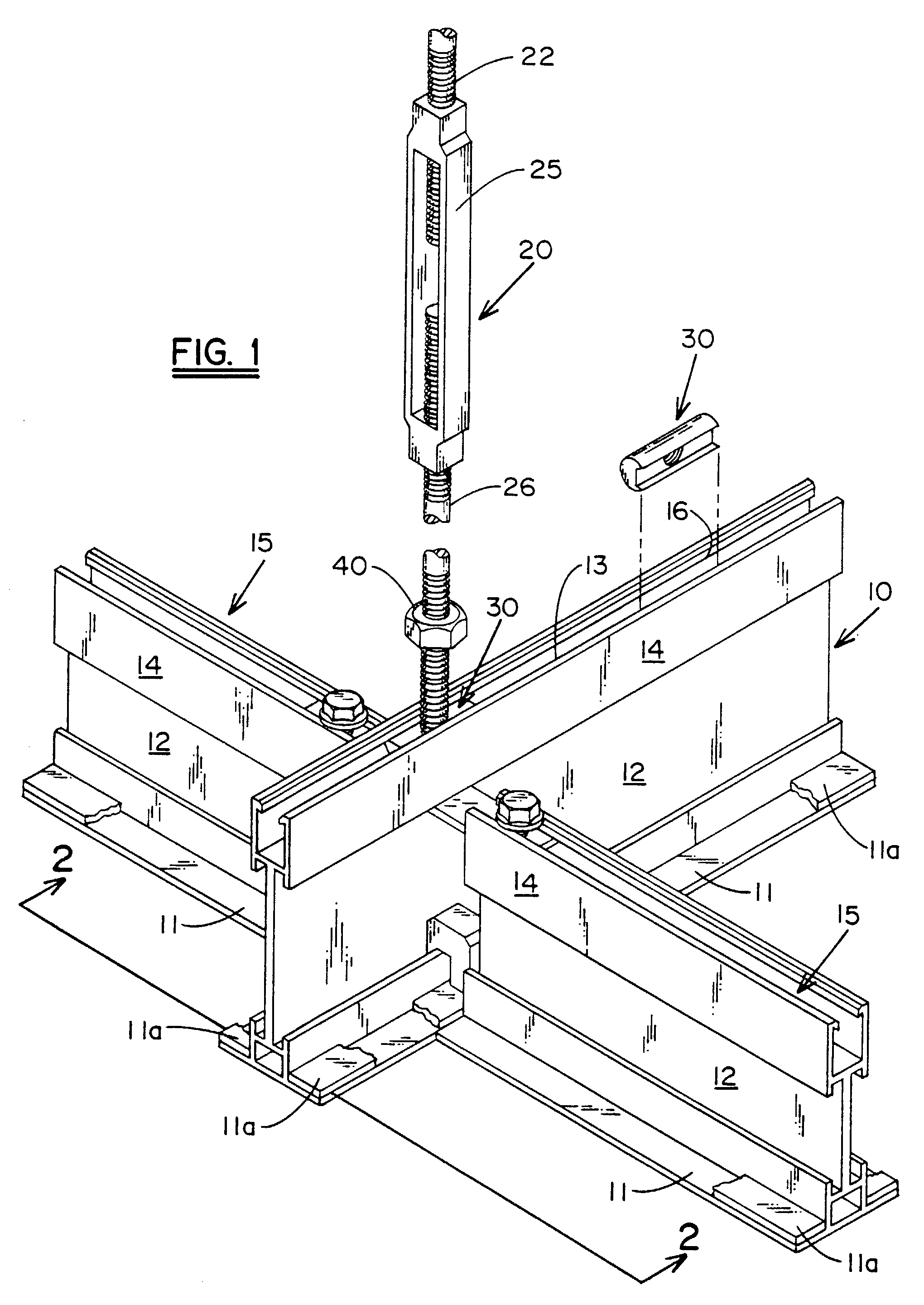
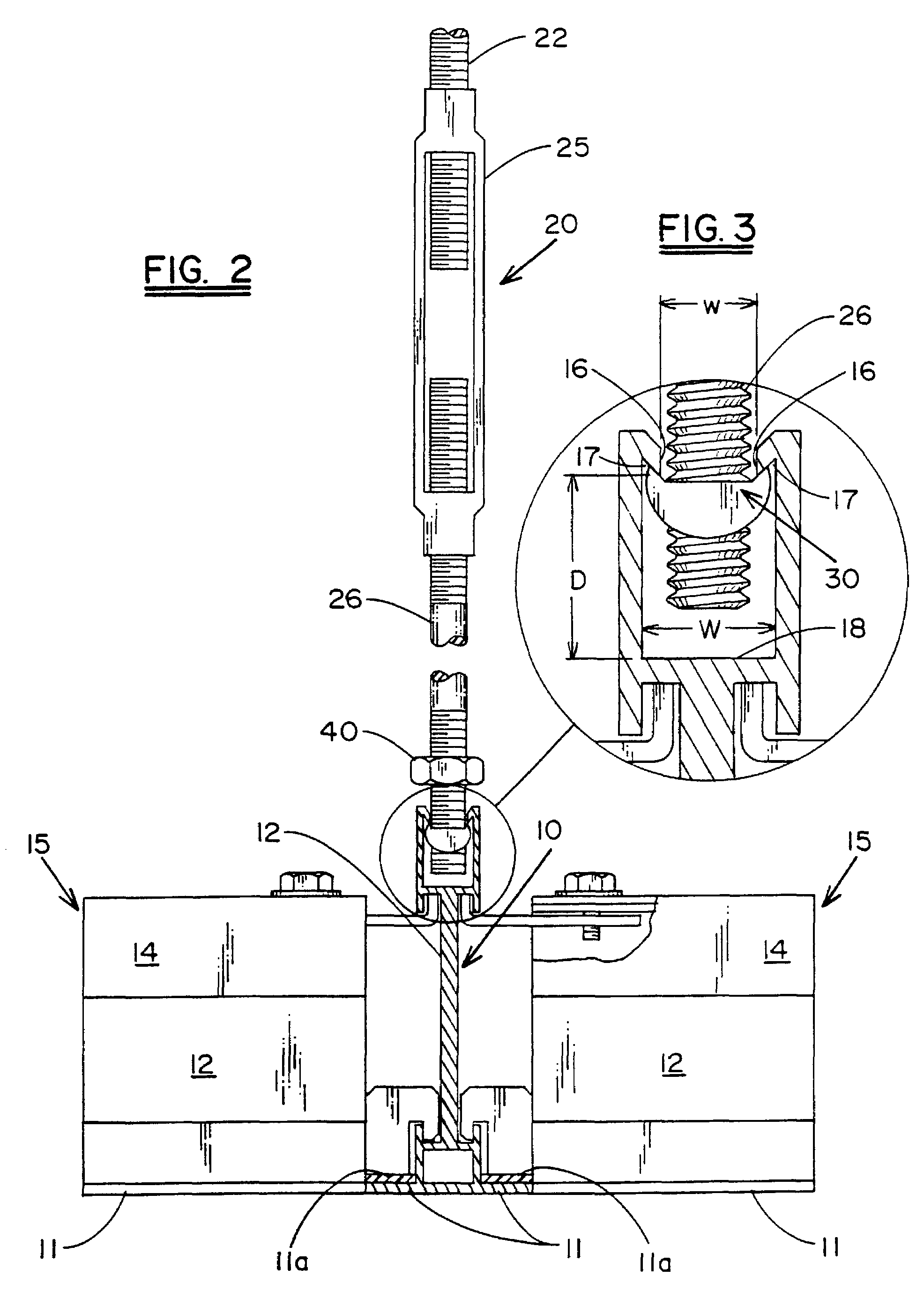
[0006]In accordance with the present invention, there is provided a threaded connector nut for engagement by a threaded coupling member for supporting a suspended ceiling grid system from an overhead support structure. The threaded connector nut is designed to be placed or dropped into an upper channel of the suspended ceiling grid system whereby, because of the configuration of the connector nut, a threaded opening formed through the connector nut will be positioned for engagement by a threaded end of the coupling member. The configuration of the connector nut facilitates ease of installation, and permits the connector nut to be located along the longitudinally extending channel to facilitate alignment with the overhead support structure.

Problems solved by technology

Such systems, however, are frequently difficult or inconvenient to install, while others are designed for use with a specific type of ceiling grid system.

Method used


Image

  • Ceiling suspension structure
  • Ceiling suspension structure
  • Ceiling suspension structure

Examples


Embodiment Construction

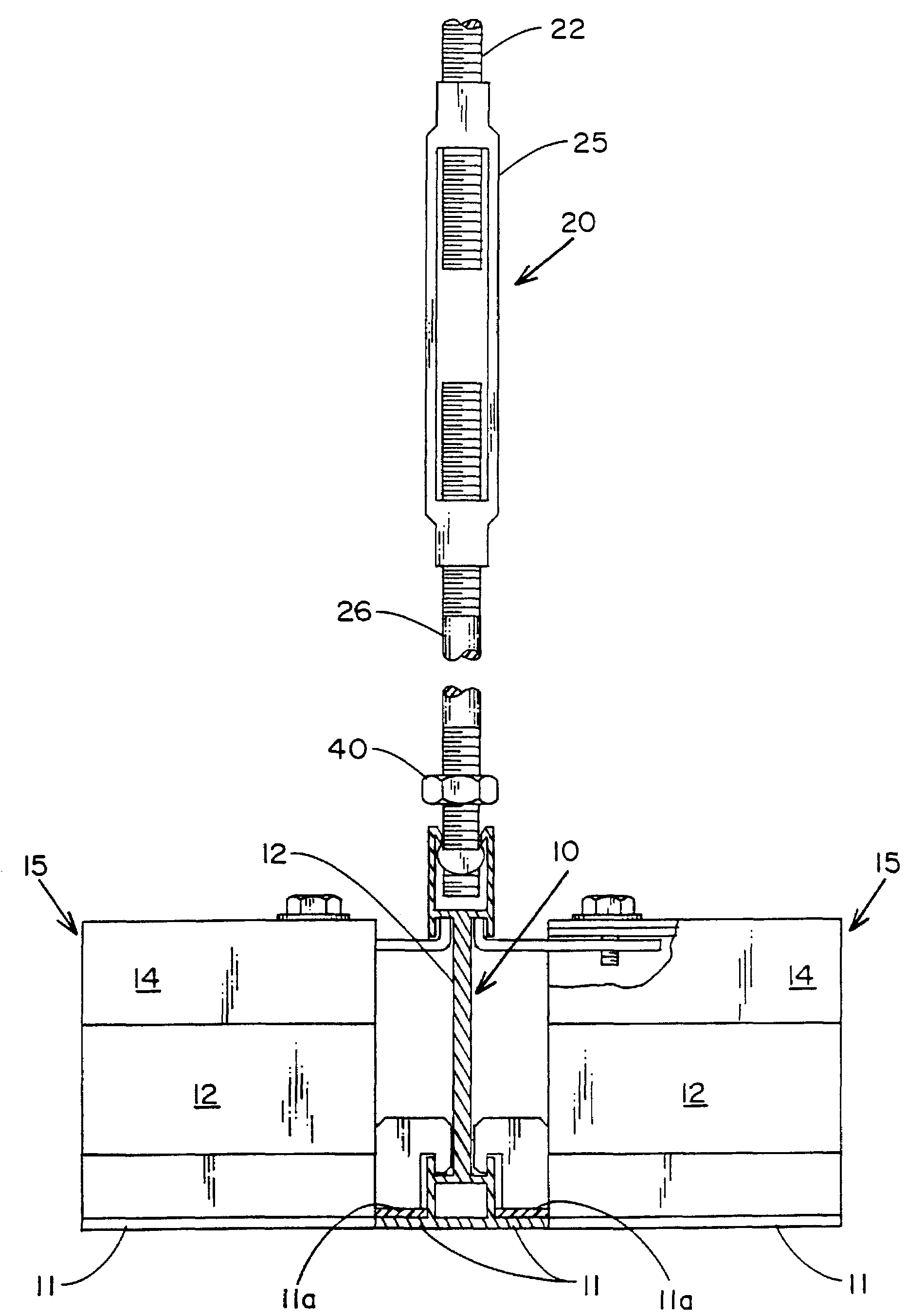
[0014]Referring now to the drawings, there is illustrated in FIGS. 1 and 2, a portion of a grid-work of a suspended ceiling system. Such a grid-work typically includes a runner 10, and connecting cross-members 15, which are secured to and held in suspension by their connection with the runners 10. Both the runners 10 and the cross-members 15 typically include an outwardly extending flange 11, at the lower portion of each of the cross-members and runners, for supporting a ceiling panel (not shown). To form a sealed overhead structure, a seal 11a may be included on the upper surface of the flange 11.

[0015]The runner 10 and cross-members 15 typically include a vertically extending chord 12 which extends upwardly from the flanged end and has at the upper portion thereof an open channel 14. The channel 14 of the cross-members is generally used for securing the cross-members 15 in a position substantially normal or perpendicular to the chord 12 of the runner 10. The open channel 14 formed...


PUM


Abstract

A threaded coupling member for supporting a suspended ceiling grid system from an overhead support structure. A threaded connector nut is designed to be placed or dropped into an upper channel of the suspended ceiling grid system whereby, because of the configuration of the connector nut, a threaded opening formed through the connector nut will be positioned for engagement by a threaded end of the coupling member.

Description

TECHNICAL FIELD[0001]This invention relates in general to suspended ceiling supports and, in particular, to a support to be used for suspending ceilings from an overhead roof or support structure for use with channeled components of a suspended ceiling grid.BACKGROUND TECHNOLOGY[0002]Suspended ceilings are frequently formed utilizing a channelled grid or frame work which is engaged by a suitable fastener to suspend the ceiling grid from an existing roof or overhead support structure. In this manner the suspended grid-work is used to form a suspended ceiling at a height above the floor. The space so formed above the ceiling can be used for various purposes such as the support of mechanical services such as heating, ventilating and air conditioning systems (HVAC) or to form an upper seal for the space below the ceiling to preserve the integrity of a particular enclosed area such as used in cleanrooms.[0003]These suspended ceiling grids are used in combination with panels which are fit...

Claims


Application Information

Patent Timeline
IPC IPC(8): E04B9/18E04B9/12E04B9/20
CPCE04B9/127E04B9/20E04B9/183
Inventor BONGIO, VINCENT J.CAVALLO, THOMAS E.
Owner SULLIVAN BAZINET BONGIO
Learn More