Remotely attachable and separable coupling

a remote attachment and separable technology, applied in the direction of electrical apparatus casings/cabinets/drawers, hoisting equipment, fire alarms, etc., can solve the problems of large time-consuming labor, manual positioning of people, and large time-consuming effort, and achieve the effect of easy engagement or disengagemen

Inactive Publication Date: 2007-10-30
ACCESSMOUNT LLC
View PDF41 Cites 142 Cited by
  • Summary
  • Abstract
  • Description
  • Claims
  • Application Information

AI Technical Summary

Benefits of technology

[0009]An assembly adapted to be secured to a ceiling or other overhead location comprises a pair of first and second subassemblies couplable and decouplable by a person standing on the floor, without manually directly contacting either, but using a rod or other elongated member. The first subassembly may be fixedly secured to the ceiling or other overhead location, hence referred to as the secured subassembly, or “base member” or “base” for brevity; the second subassembly, which provides a surface to which an article is secured, for example a hook or an electrical fixture, is removably coupled to the base; because the second subassembly is used to mount the article which is to be suspended, or, is itself provided by the base of the article to be suspended, the second assembly is referred to as the suspended subassembly, or “mounting member” or “mount” for brevity. The two subassemblies, namely, the base and mount, are coupled to one another with remotely uncouplable coupling means, for example, magnetically, or, with mating hooks and eyelets such as are provided with Velcro® fasteners adhesively secured within the base and mount respectively, or, by a detent means integrally formed with the base and mount, such as a peripheral detent, or, a latching means, or, an interference fit. A rod-acceptance means, such as a socket, or finger-like protrusion, or through-passage in the mount, also functions as a detachment means, depending upon whether the mount is to be positioned on the base, or removed from it; when the rod-acceptance means is a rod-attachment means, it is secured to the mount, or may be integrally formed therewith, and is adapted to be interfitted to one end of a rod so as to be securely supported by it. When a force is exerted on the rod by a person manipulating it from the floor of the room, the mount is easily engaged with, or disengaged from the base, the mechanical advantage arising from the use of a long rod as a lever. The dimensions of the mount may be so chosen that it be mated to the base with effortless accuracy; a decoupling force adequate to disengage the mount from the base is exerted on the end of the rod to remove the mount after it is mated. The decoupling force required to decouple the subassemblies depends upon the coupling force exerted by the coupling means, and the decoupling force exerted is increased by the length of the rod which provides the leverage.

Problems solved by technology

The problem: how does a person locate and manually secure an article on a high, out-of-reach ceiling or other overhead location without using something to stand on, for example, a step-ladder.
This is typically a time-consuming effort usually carried out after a store is closed for the day, and requires that an employee drag a step-ladder from one sign to the next one which is to be changed, or to use a motorized scissor-jack to travel from one to the other and change it.
The hooks are used to suspend balloons and streamers, which are required to be changed for each occasion, entailing a substantial amount of time-consuming labor.
The simple task of inserting a hook into the eye of an eye-bolt on the ceiling, or snagging a hook on the ceiling with another hook from which a bunch of balloons is hung, while standing on a step-ladder is a trying and time-consuming task.
As anyone who has replaced batteries in a smoke alarm secured to the ceiling is well aware, enthusiasm for changing the battery, immediately upon noting that it must be changed, is inhibited, and the task is complicated, by having to climb onto a step-ladder while removing and replacing the battery with outstretched arms.
The difficulty of the simple task is greatly exaggerated if the steel plate is to be registered to the magnet on a ceiling which cannot be reached with a conveniently available step-ladder, the higher the ceiling, the more daunting the task, and certainly impossible if the person is in a wheelchair.

Method used


Image

  • Remotely attachable and separable coupling
  • Remotely attachable and separable coupling
  • Remotely attachable and separable coupling

Examples


Embodiment Construction

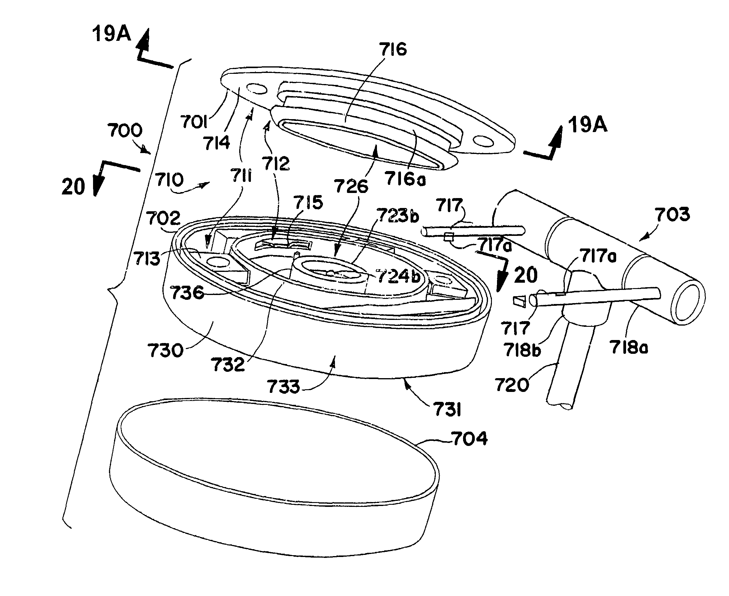
[0127]Several additional embodiments of remotely attachable and separable coupling system according to the present invention are illustrated in FIGS. 17-36. In these embodiments the retention mechanism that retains the mount and base member together would be hidden from normal view when the system is assembled. Thus, the complete system has an aesthetically pleasing structure, while maintaining the basic functionality of the previously described embodiments.

[0128]Referring briefly to FIGS. 17-21, a remotely attachable and separable coupling system 700 includes both the mentioned “hidden” feature and a dual retention mechanism. The system 700 includes a base member 701, a mount 702, and an installation and removal tool 703. The base member 701 is intended to be secured to a fixed structure or to some other device, and the mount 702 mates to the base member 701. Removal and installation of the mount 702 is accomplished through the use of the installation and removal tool 703. The inst...


PUM


Abstract

An article for mounting from or against the ceiling is removably coupled to a base fixedly secured to the ceiling, by a person standing on the floor, supporting the article on an elongated rod, and thrusting the article against the base to couple the article and the secured base. The article is removed by inserting the rod into the article, exerting a force on the rod to uncouple the article from the base, and supporting the article on the rod as the article is lowered. The article is thus positioned on or hung from the ceiling, without being manually contacted by the person. The article may be used to mount other devices, such as a sign, smoke detector, etc. or may include such device as a part of the mount.

Description

TECHNICAL FIELD[0001]The present invention relates to an improvement in access means for an assembly located on a room's ceiling or other overhead location, by a human manipulating the assembly while standing on the room's floor; seated in a wheelchair, or otherwise unable to reach the assembly unassisted. The primary purpose of the assembly is to suspend an article, such as a sign, or, pendently support a device, such as a smoke detector and alarm or other electrically actuated fixture, which, of necessity, is to be secured to the ceiling, and periodically removed for renewal, maintenance or inspection. The assembly of the invention also may be used to mount or to support various devices from a wall, ceiling, pole, or virtually any other member, part or the like; and / or the assembly may be included as part of such device.BACKGROUND[0002]Magnetic holders such as are disclosed in U.S. Pat. No. 5,472,163 to Callas are used to display signs on upright metal supports. A permanent magnet...

Claims


Application Information

Patent Timeline
Patent Type & Authority Patents(United States)
IPC IPC(8): F16M13/00F16B1/02H02G3/20
CPCH02G3/20G08B17/10G08B29/145G08B17/113
Inventor PITLOR, NELSON DOUGLAS
Owner ACCESSMOUNT LLC
Why Eureka
Try Eureka