OLED display with composite photosensor

a composite photosensor and oled display technology, applied in static indicating devices, photometry using electric radiation detectors, instruments, etc., can solve the problems of reducing the light emitted by half, reducing the efficiency of organic materials in the device, and not being able to provide real-time operation, etc., to maximize the light output

Active Publication Date: 2007-10-30
GLOBAL OLED TECH
View PDF16 Cites 142 Cited by
  • Summary
  • Abstract
  • Description
  • Claims
  • Application Information

AI Technical Summary

Problems solved by technology

However, as the display is used, the organic materials in the device age and become less efficient at emitting light.
If the portion of the light emitted toward the back is absorbed, it is absorbed and lost, thereby reducing the light emitted by one half.
This approach has the problem that the sensor device obscures the display during the calibration and is not capable of providing real time operation.
Moreover, these approaches are not useful for correcting uniformity variations among individual pixel display elements.
This arrangement fails to provide adequate sensitivity for sensing ambient illumination in an actual device and does not provide feed-back on the OLED light output uniformity.

Method used


Image

  • OLED display with composite photosensor
  • OLED display with composite photosensor
  • OLED display with composite photosensor

Examples


Embodiment Construction

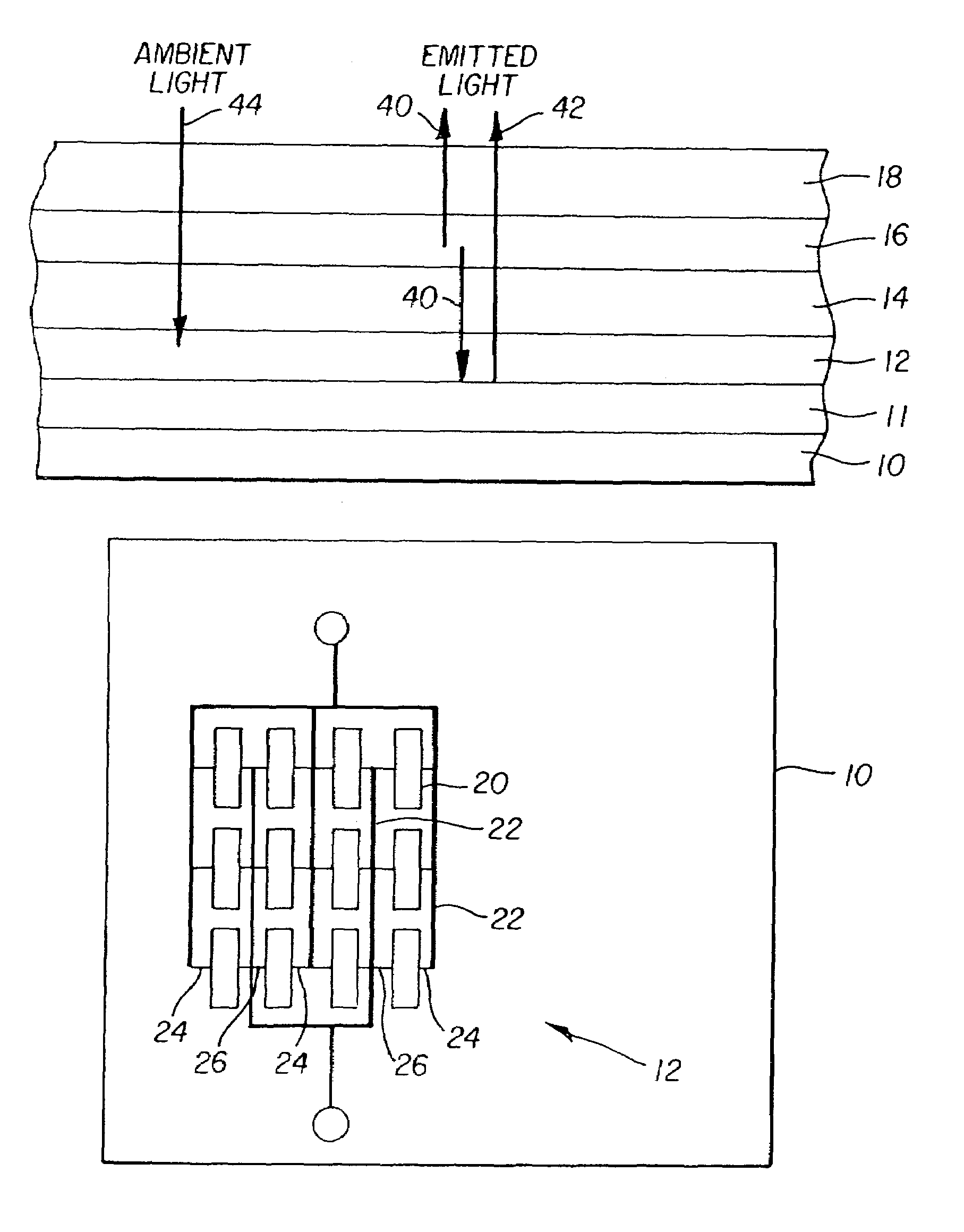
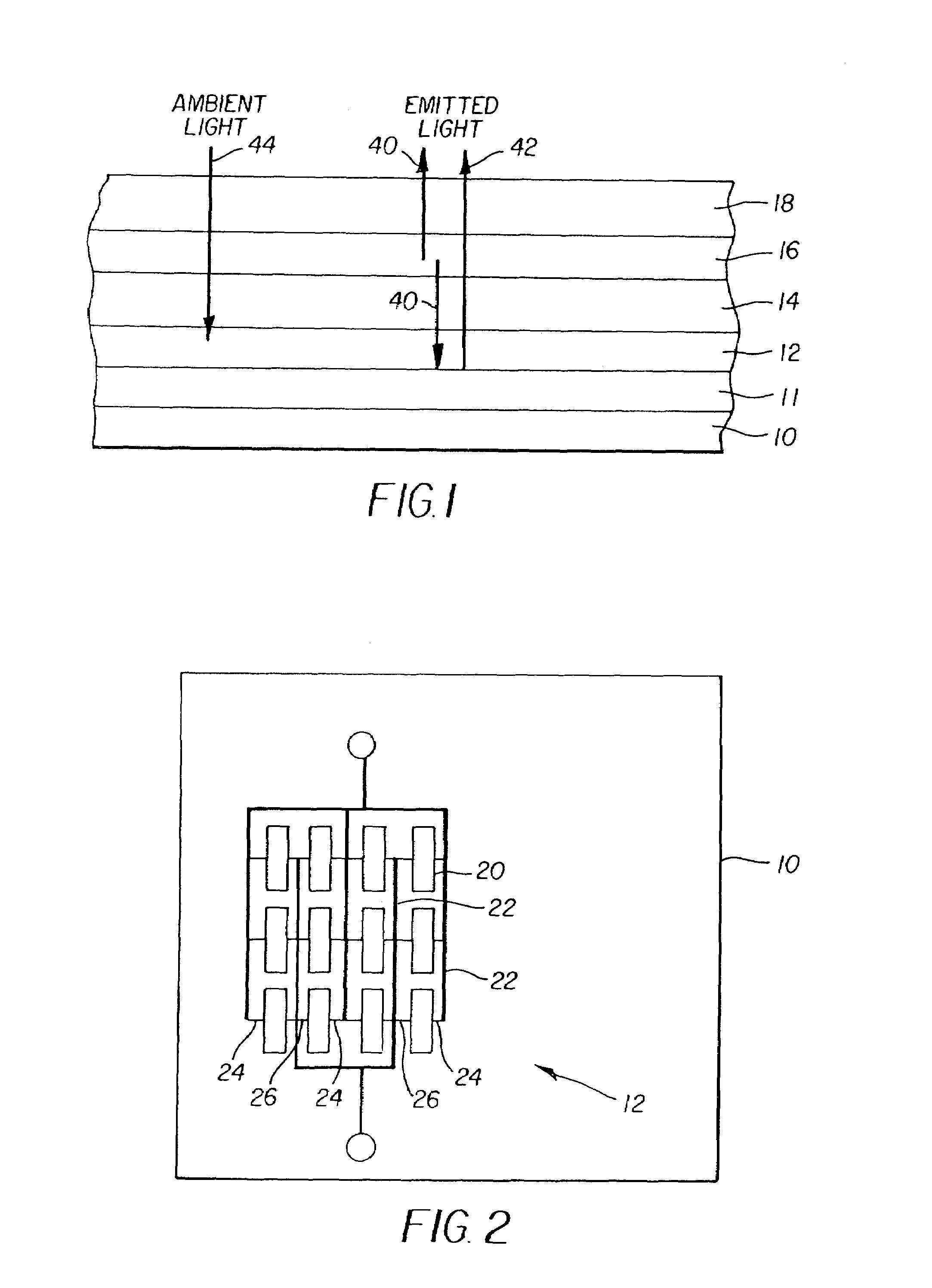
[0020]Referring to FIG. 1, a top-emitter OLED display and photo-sensor, comprises a substrate 10; a composite light sensor layer 12 located over the substrate comprising a plurality of thin-film light sensitive elements connected in parallel; a first transparent electrode 14 located over the plurality of thin-film light sensitive elements; one or more organic layers 16 comprising an OLED located on the transparent electrode 14 and emitting light through the transparent electrode 14; and a second electrode 18 located on the one or more organic layers 16 comprising an OLED. An additional reflective layer 11 may be provided above the substrate beneath the plurality of light sensitive elements in layer 12. In the top-emitter configuration shown in FIG. 1, the second electrode 18 must also be transparent. A planarizing layer, not shown, may be employed between the composite light sensor layer 12 and the transparent electrode 14.

[0021]Referring to FIG. 2, in a top view, composite light se...


PUM


Abstract

An OLED display and photo-sensor is described, comprising: a substrate; a composite light sensor made up of a plurality of individual thin-film light sensitive elements located over the substrate and connected in parallel to provide a common signal; a first transparent electrode located over the composite light sensor; one or more organic layers comprising an OLED located on the transparent electrode and emitting light through the transparent electrode and to the composite light sensor; and a second electrode located on the one or more organic layers comprising an OLED. The OLED display device provides a means to measure the light output of the OLED display device while maximizing the light output and is useful in measuring incident ambient illumination.

Description

FIELD OF THE INVENTION[0001]The present invention relates to solid-state OLED flat-panel displays and, more particularly, to such displays having photosensors integrated into the display.BACKGROUND OF THE INVENTION[0002]Solid-state organic light emitting diode (OLED) image displays are of great interest as a superior flat-panel display technology. These displays utilize current passing through thin films of organic material to generate light. The color of light emitted and the efficiency of the energy conversion from current to light are determined by the composition of the organic thin-film material. Different organic materials emit different colors of light. However, as the display is used, the organic materials in the device age and become less efficient at emitting light. It is useful, therefore, to provide a means to correct the light output of an OLED device over time. It is also useful to detect the ambient illumination incident on an OLED display and to modify the brightness...

Claims


Application Information

Patent Timeline
Patent Type & Authority Patents(United States)
IPC IPC(8): G01J1/44G09G3/30H01L27/00H01L27/15H01L27/32H05B33/00
CPCH01L27/3269H10K59/13
Inventor COK, RONALD S.
Owner GLOBAL OLED TECH
Why Eureka
Try Eureka