
Method and apparatus for adjusting color edge center in color transient improvement

a color transient improvement and center adjustment technology, applied in the field of video signal processing, can solve the problems of color edge smearing in received/displayed images, weak high-pass filter response near the center of the color edge,

Inactive Publication Date: 2007-10-30
SAMSUNG ELECTRONICS CO LTD
View PDF6 Cites 13 Cited by
  • Summary
  • Abstract
  • Description
  • Claims
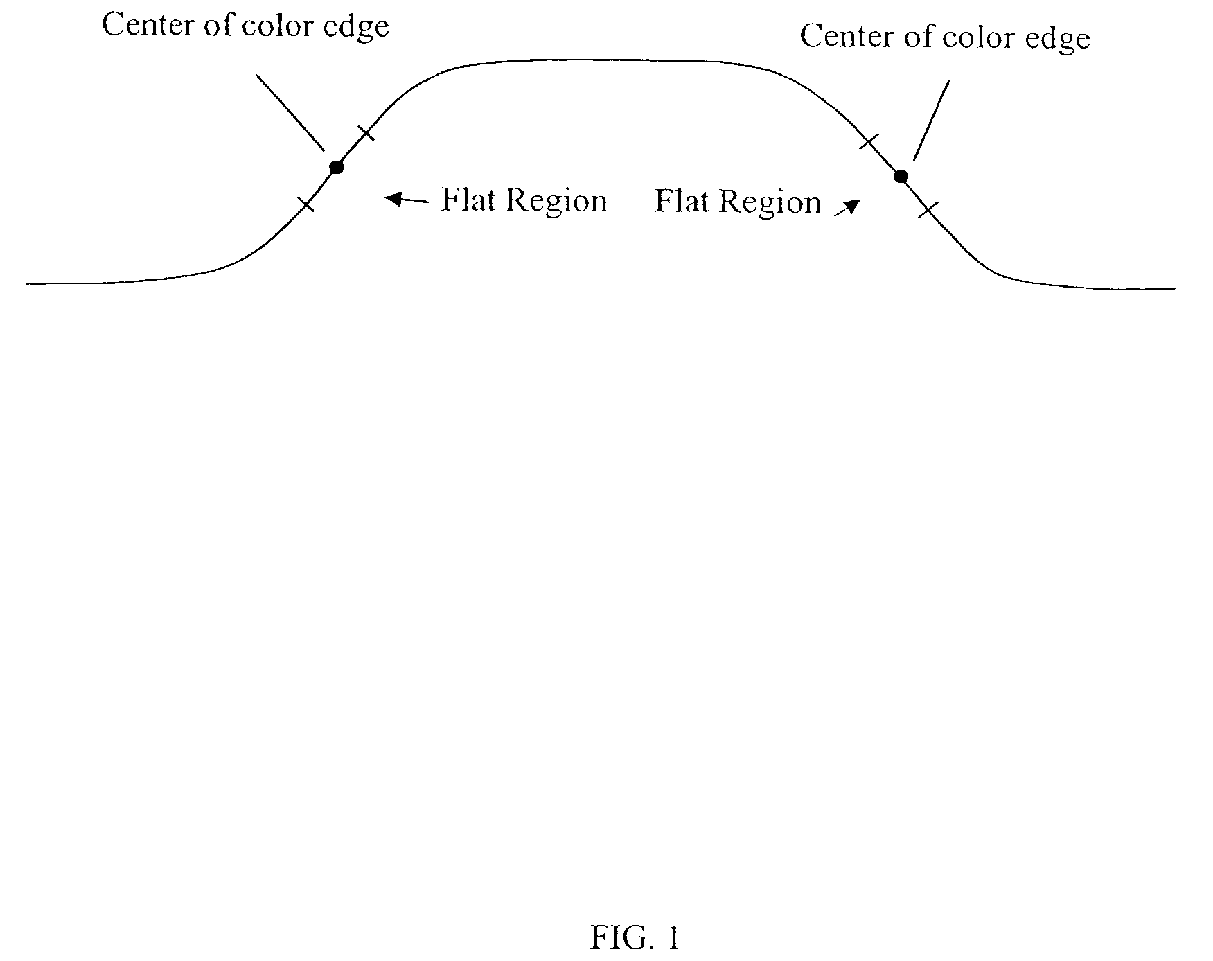
  • Application Information

AI Technical Summary

Benefits of technology

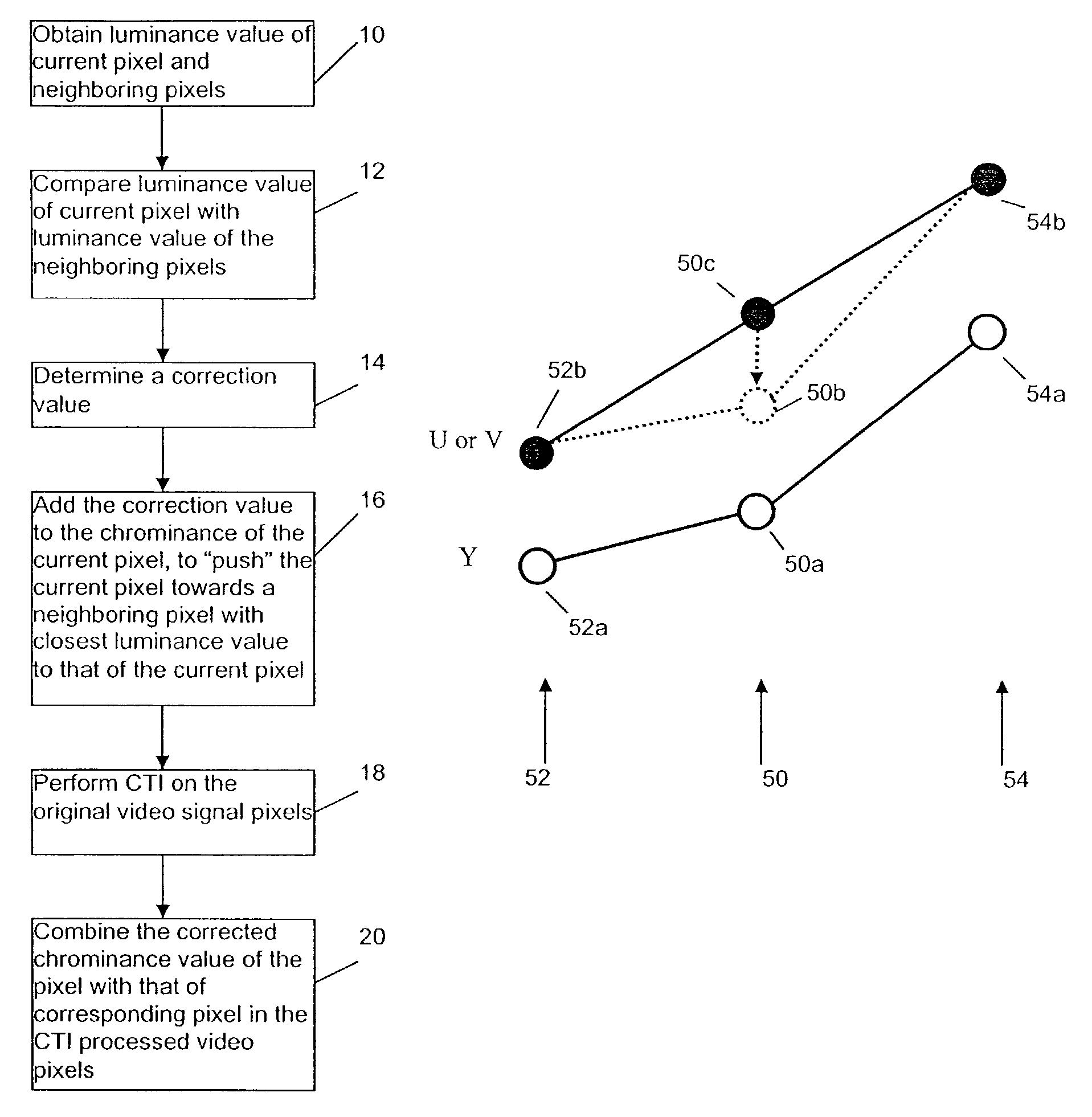
[0006]The present invention addresses the above needs. An object of the present invention is to provide a method to properly process the “flat” region near the center of the color transition to restore the frequency components lost due to the limited bandwidth. To achieve that goal, in one embodiment the present invention provides a method and apparatus to enhance color transients in input video signals including chrominance and luminance signals that represent video frames comprising pixels of video information. Initially, the first derivatives, including left and right derivatives, of both the input chrominance signal and luminance signal are computed. Based on the computed first derivatives of the chrominance and luminance signals, two correction signals are computed.
[0010]Therefore, an enhancement method according to the present invention sufficiently sharpens the slope of the color transient and processes the “flat” region near the center of the color transition to restore the frequency components lost due to the limited bandwidth. Further, such a method can be used in conjunction with conventional methods, to process the video signal according to CTI methods when the second derivative of the input chrominance signal is large.

Problems solved by technology

The limited bandwidth of the chrominance signal produces relatively slow chrominance transitions, causing smeared color edges in the received / displayed images.
Therefore, the high-pass filter response near the center of the color edge is very weak.

Method used


Image

  • Method and apparatus for adjusting color edge center in color transient improvement
  • Method and apparatus for adjusting color edge center in color transient improvement
  • Method and apparatus for adjusting color edge center in color transient improvement

Examples


example implementations

[0026]To help understanding, in the following, examples of the present invention are described using chrominance signalU. However as those skilled in the art recognize, the present invention is useful with chrominance signals U and V, and other characteristic signals. Further, to help understanding the examples below are described for horizontal processing (i.e., comparison of luminance value of a pixels with that of its left and right neighboring pixels). However as those skilled in the art recognize, vertical processing (i.e., comparison with upper and lower neighboring pixels) is similar to the horizontal processing, and is contemplated by the present invention.

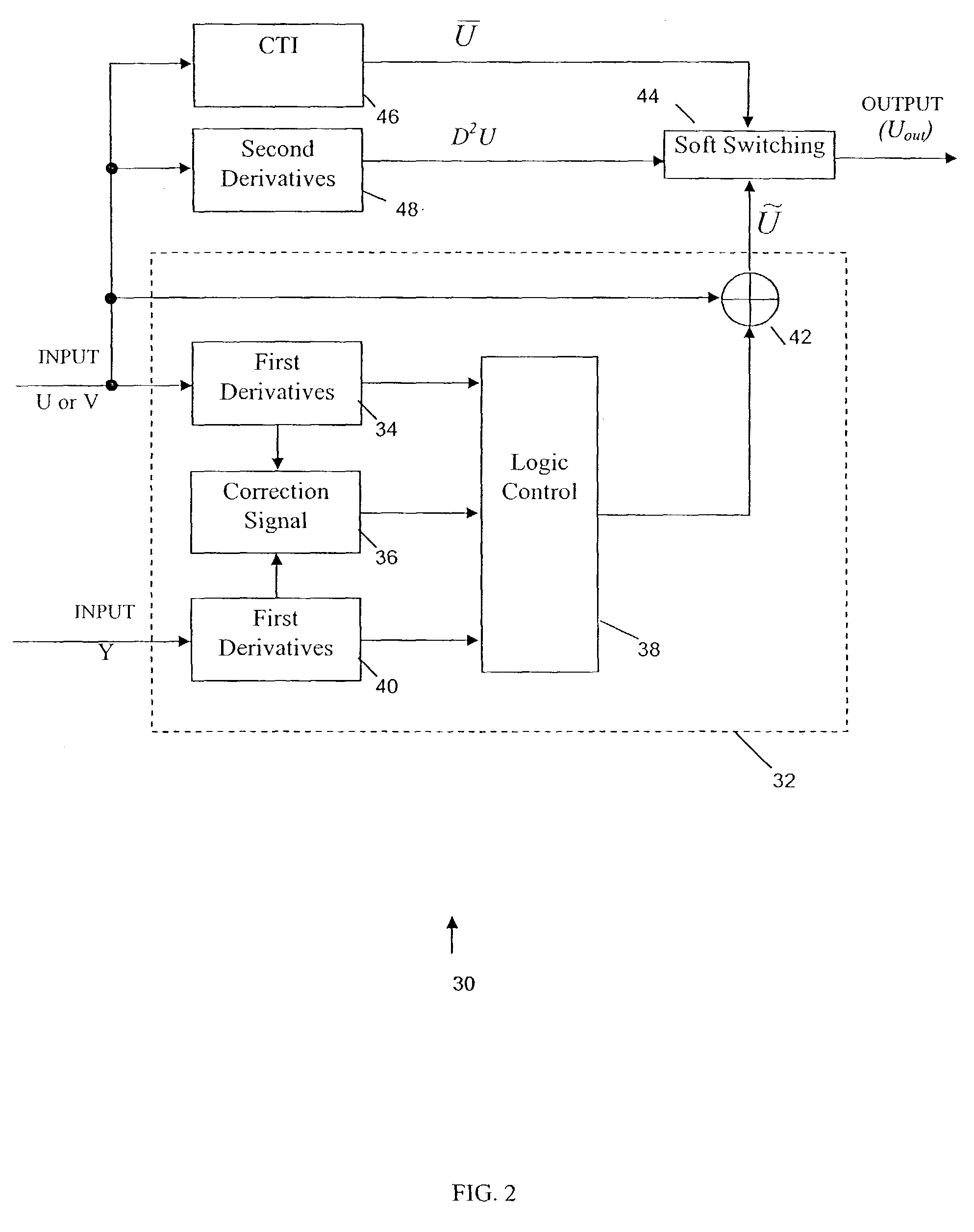
[0027]FIG. 2B shows a block diagram of a preferred embodiment of a video processing system 30 implementing the above enhancement method according to the present. In a chrominance correction section 32, the input chrominance signal is first supplied to a First Derivatives Calculator 34 for the chrominance signal U. The Firs...


PUM


Abstract

An improved method for color transient enhancement in an input video frame of pixels. The luminance value of a current pixel is compared to that of neighboring pixels. A correction value is determined and the chrominance value of the current pixel is “pushed” towards the neighboring pixel that has a luminance value closest to that of the current pixel, by adding the correction value to the current pixel's chrominance value. The original video frame is also separately processed using a CTI method, and the current pixel's corrected chrominance value is combined with the corresponding pixel in the output of the CTI processing by soft switching unit to generate an output video frame that is an enhanced version of the input video frame.

Description

FIELD OF THE INVENTION[0001]The present invention relates generally to video signal processing, and more particularly to chrominance signal processing to enhance color transients.BACKGROUND OF THE INVENTION[0002]In color TV broadcasting standards, such as NTSC, PAL and SECAM, the transmitted signals include chrominance signals and luminance signals. In comparison to the luminance signal bandwidth, the chrominance signal bandwidth is rather narrow. The limited bandwidth of the chrominance signal produces relatively slow chrominance transitions, causing smeared color edges in the received / displayed images.[0003]Different techniques have been used in attempts to enhance the sharpness of color transitions, such as those described in U.S. Pat. No. 4,935,806 and U.S. Pat. No. 5,920,357, known as “Color Transient Improvement(CTI)” techniques. The basic steps in the Color Transient Improvement techniques are to add a high-pass filtered signal, such as the second derivative of the original s...

Claims


Application Information

Patent Timeline
IPC IPC(8): H04N5/21H04N9/77H04N9/64
CPCG06T5/50H04N19/80G06T5/003H04N19/117H04N19/186H04N19/182H04N9/646G06T2207/10016G06T2207/10024G06T2207/20012G06T2207/20192G06T5/73H02K41/031G03B3/10H02K2213/03
Inventor LIN, PENGKIM, YEONG-TAEG
Owner SAMSUNG ELECTRONICS CO LTD
Learn More