Method for producing chain link and a corresponding chain link of a cable drag chain

a technology of drag chain and chain link, which is applied in the direction of mechanical equipment, machine supports, other domestic objects, etc., can solve the problem of unreleasable connection of the crosspiece to the pla

Inactive Publication Date: 2007-11-06
KABELSCHLEPP GMBH
View PDF19 Cites 17 Cited by
  • Summary
  • Abstract
  • Description
  • Claims
  • Application Information

AI Technical Summary

Benefits of technology

[0005]The present invention provides an easier method for assembling link plates and crosspieces with a fewer number

Problems solved by technology

This crosspiece is connecte

Method used


Image

  • Method for producing chain link and a corresponding chain link of a cable drag chain
  • Method for producing chain link and a corresponding chain link of a cable drag chain
  • Method for producing chain link and a corresponding chain link of a cable drag chain

Examples


Embodiment Construction

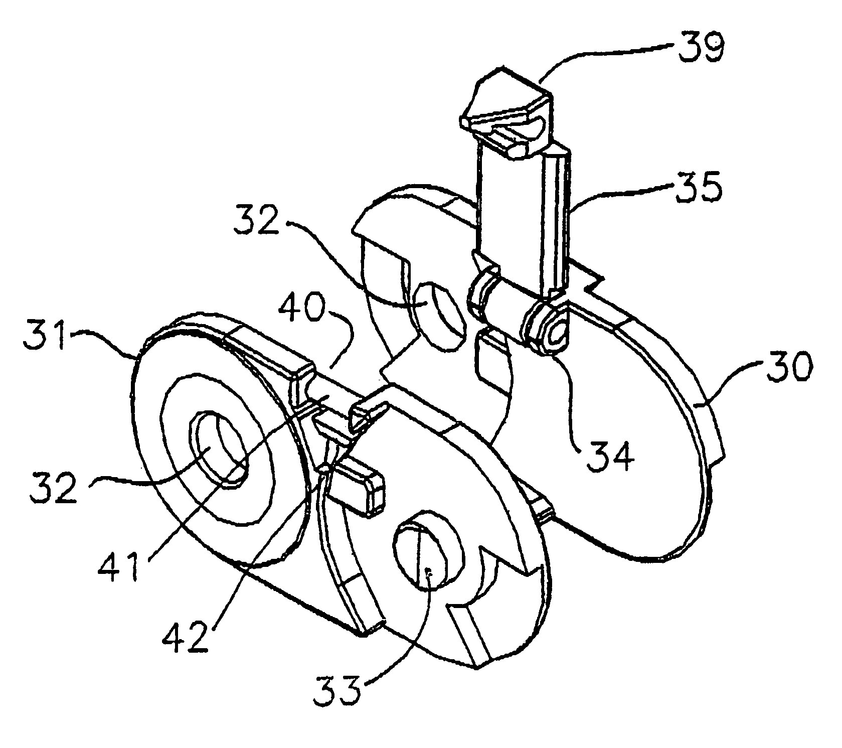
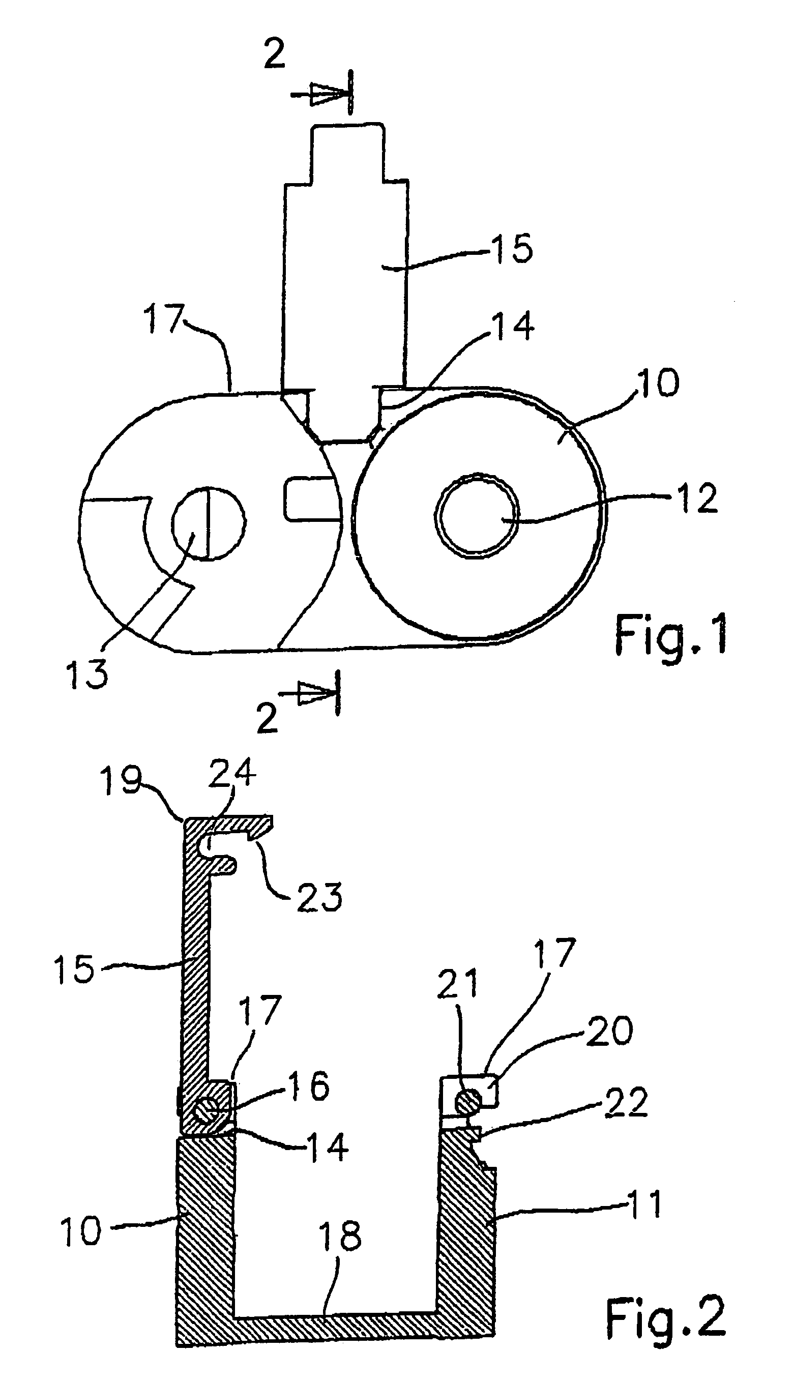
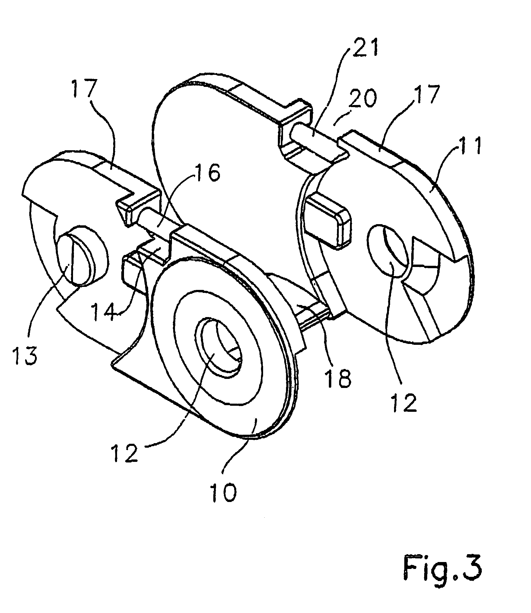
[0040]FIGS. 1 to 3 illustrate one embodiment of a chain link according to the present invention.

[0041]The link is provided for a power transfer chain that can include a number of such chain links. The chain link has two spaced plates 10, 11. In the depicted example, the plates 10, 11 are joined by a lower rigid crosspiece 18. Each plate 10, 11 has a hole 12 on one end region (FIG. 3). A pivot 13 is provided in the opposite end region of the plates 10, 11. For reference in the claims, plate 11 is the “first plate” and the plate 10 is the “second plate.” The holes 12 or pivots 13 of the chain plates 10, 11 are shaped and sized so that a pivot 13 can be inserted into the hole 12 of a link plate of an adjacent chain link, and several link plates can be joined together to form a strand. This design of a power transfer chain in known per se.

[0042]On an upper edge 17 of the plate 10 and across the longitudinal extent of the plate 10, a recess 14 is provided. A link axis 16 is formed within...


PUM


Abstract

The invention relates to a method for producing a plastic chain link, which has interspaced plates (10, 11) as well as lower and upper cross-connecting elements (15) that connect said plates, whereby at least one cross-connecting element is connected to one of the plates (10) in an articulated manner. According to the invention, at least one of the plates is firstly produced followed by the production of at least one of the cross-connecting elements while simultaneously forming a joint connection between one of the plates and one of the cross-connecting elements.

Description

[0001]The present invention relates to a method for producing a chain link, and particularly to a chain link for a power transfer chain.[0002]A chain link for a power transfer chain is known from DE 43 13 075 A1, which has two opposite link plates spaced apart from each other. The link plates are connected by a crosspiece. The crosspiece and link plates can be connected by releasable hinges that can be locked together. For this purpose, the crosspiece according to DE 43 13 075 A1 has shoulders on both sides that are connected to pivots with a round cross-section. The link plates have slits to accommodate the shoulders. In the region of the slits, the side plates have recesses for locking the combination and guiding of the pivots. By this configuration of the hinges, pivoting of the crosspiece by 180° is made possible, so that the crosspiece can be brought into any position.[0003]Another variant of a chain link for a power transfer chain is known from DE 33 18 565 C2. The chain link ...

Claims


Application Information

Patent Timeline
IPC IPC(8): F16G13/00F16G13/16
CPCF16G13/16
Inventor WEBER, WILLIBALDWEHLER, HERBERT
Owner KABELSCHLEPP GMBH
Why Eureka
Try Eureka