Stapler safety device to limit motion of striker

a safety device and striker technology, applied in the field of safety mechanisms, can solve the problems unable to control the movement of manual staplers, etc., and achieve the effect of preventing the ejection of staples

Active Publication Date: 2007-11-06
WORKTOOLS
View PDF58 Cites 43 Cited by
  • Summary
  • Abstract
  • Description
  • Claims
  • Application Information

AI Technical Summary

Benefits of technology

[0010]One approach to disable a manual stapler is to interfere with the movement of the power spring / striker combination. Specifically, the safety mechanism can limit the upward movement of the power spring / striker to keep it from reaching the release point, or the safety mechanism can obstruct the downward movement of the power spring / striker after release thus preventing the ejection of a staple.
[0012]In a common design for a spring-actuated stapler, a striker has a rest position in front of a staple track. Pressing a handle causes the striker to rise in the stapler toward a release point where spring bias accelerates the striker toward and into the staple to eject the staple out from the stapler. In the present invention, a locking device prevents the striker from being released suddenly unless the stapler is pressed against a working surface. In various embodiments, the safety device substantially immobilizes the striker, limits the upward motion of the striker / power spring assembly to a position below that release point, limits the movement of the handle preventing release of the striker / power spring assembly, and / or limits the downward movement of the striker / power spring assembly after the release point is reached. Accordingly, the striker cannot be inadvertently released and the stapler accidentally fired at full force.

Problems solved by technology

One approach to disable a manual stapler is to interfere with the movement of the power spring / striker combination.

Method used


Image

  • Stapler safety device to limit motion of striker
  • Stapler safety device to limit motion of striker
  • Stapler safety device to limit motion of striker

Examples


Embodiment Construction

[0034]The present invention in various exemplary embodiments is directed to a safety mechanism useful in spring-actuated, spring energized, or similar self-powered type tools used in dispensing and driving fasteners. Examples include manual staplers, air powered industrial staplers, spring-actuated desktop staplers, spring powered staple guns, nail guns, and the like. The present invention safety mechanisms are intended to prevent a staple or like fastener from unintentionally or accidentally being ejected out of the stapling tool.

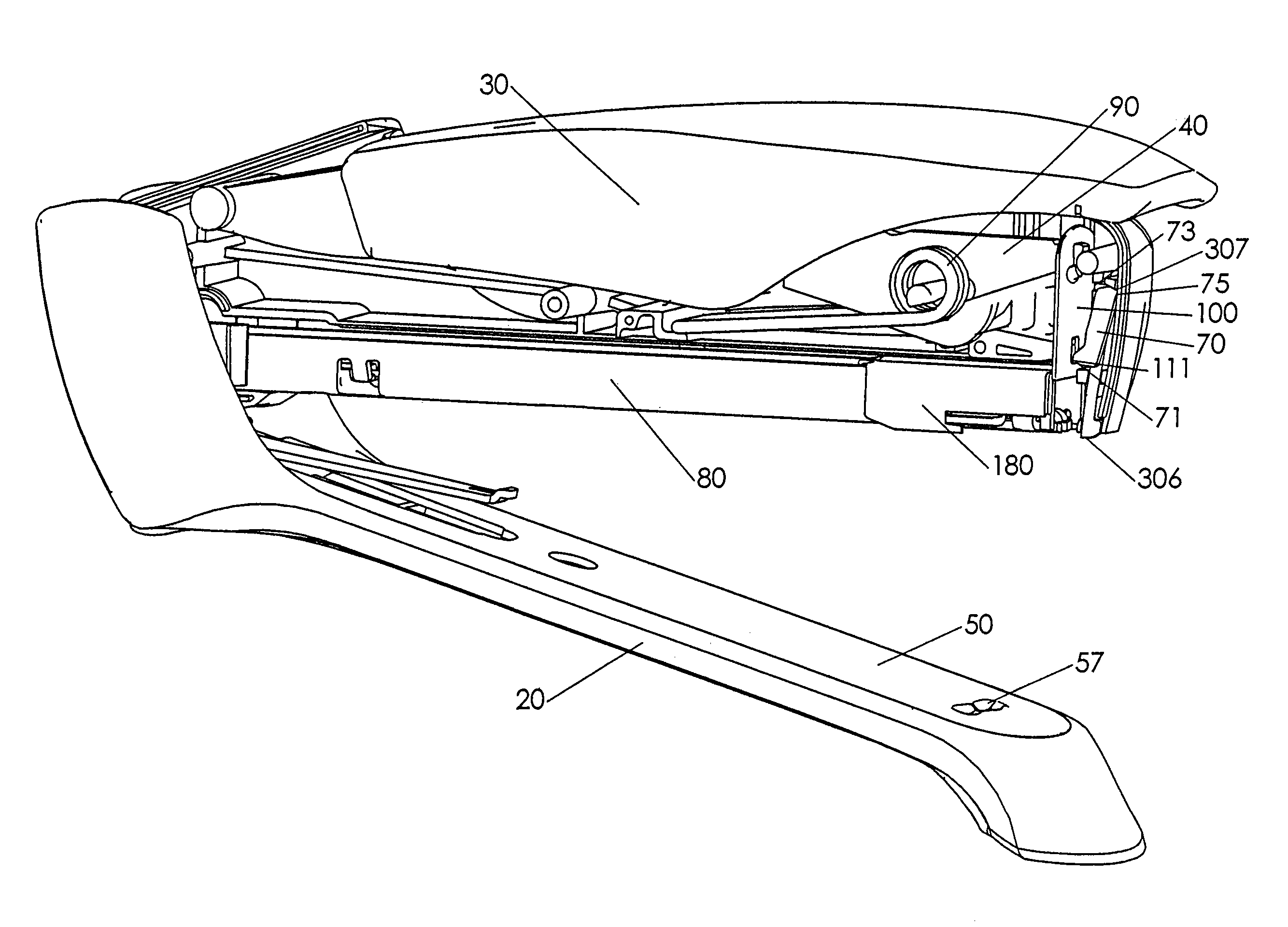
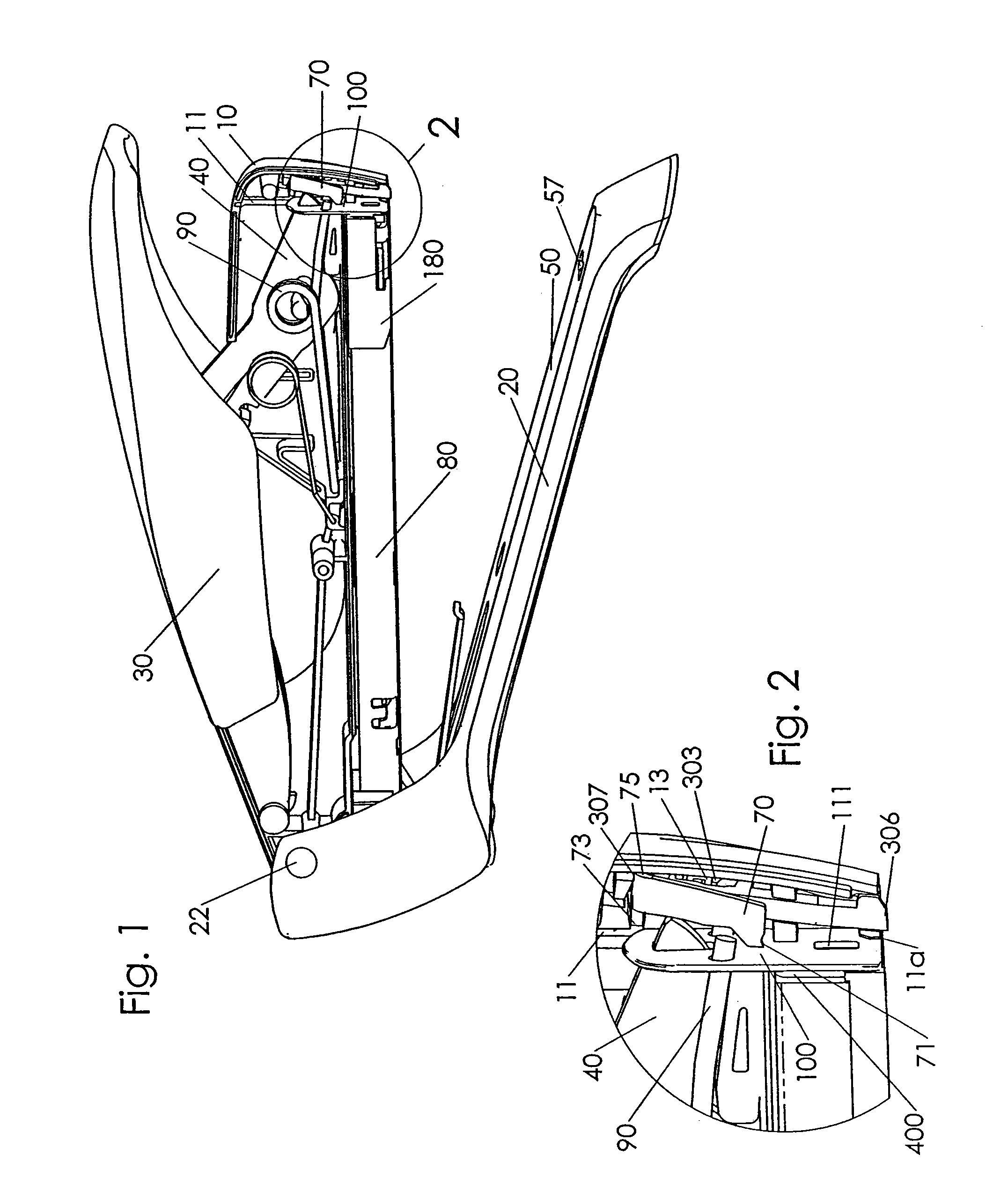
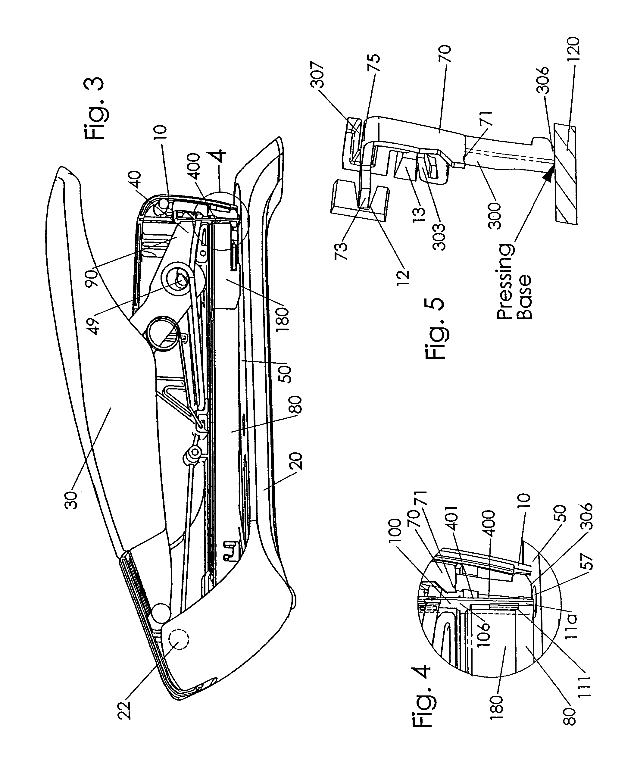
[0035]FIG. 1 is a side elevational view of a low-start type spring powered stapler with half of the housing removed to expose the interior components. In a preferred embodiment of the present invention, the spring powered stapler incorporates a safety mechanism that presents an obstruction to the internal moving components thus preventing a staple from being inadvertently ejected.

[0036]Striker 100 reciprocates vertically within striker slot 11, traversing ...


PUM

PropertyMeasurementUnit
areaaaaaaaaaaa
pressureaaaaaaaaaa
energyaaaaaaaaaa

Abstract

A safety mechanism to prevent unintended ejection of a staple or fastener in a stapler or fastening tool. A low-start version of the stapler has a handle that when pressed pivots a lever which lifts a striker and energizes a power spring. At the release point, the striker is released and accelerated under spring bias into a staple, ejecting the staple by impact blow. A high-start version has the striker stationary in the upper position as the power spring is energized. In the safety mechanism, a movable hook or arm selectively prevents the striker, and linked components thereto, from completing an operational cycle.

Description

CROSS-REFERENCE TO RELATED APPLICATIONS[0001]This application is a divisional of application having Ser. No. 11 / 305,773, filed Dec. 15, 2005, which is a continuation-in-part of application Ser. No. 11 / 064,493, filed Feb. 23, 2005, now U.S. Pat. No. 7,124,922, by the same inventor, all of whose contents are hereby incorporated by reference.FIELD OF THE INVENTION[0002]The present invention relates to spring-actuated staplers and similar self-powered tools for dispensing and driving fasteners. More precisely, the present invention relates to a safety mechanism for such staplers or tools.BACKGROUND OF THE INVENTION[0003]Staplers and related stapling devices eject staples out from a loading track into a work piece. Staplers are commonly known in two general forms or applications. A staple gun inserts a staple substantially unchanged into a work piece such as wood. A desktop stapler presses a staple against an anvil whereby the staple legs are bent behind sheets of paper. In either type o...

Claims


Application Information

Patent Timeline
Patent Type & Authority Patents(United States)
IPC IPC(8): B25C1/04
CPCB25C1/008B25C5/11B25C5/0292B25C5/0242
Inventor MARKS, JOEL S.
Owner WORKTOOLS
Why Eureka
Try Eureka