Laser machining of a workpiece

a technology of workpieces and lasers, applied in the direction of laser beam welding apparatus, basic electric elements, electrical apparatus, etc., can solve the problems of only difficult control of the thickness of the liquid layer, the inability to efficiently and accurately machining the workpiece, and the inability to use cutting gas, so as to achieve the effect of efficiently machining the workpiece and preventing the ejection of the liquid layer

Active Publication Date: 2010-06-01
SYNOVA SA
View PDF11 Cites 24 Cited by
  • Summary
  • Abstract
  • Description
  • Claims
  • Application Information

AI Technical Summary

Benefits of technology

[0011]The object of the invention is to provide a method belonging to the technical field initially mentioned, which avoids said disadvantages of the known methods and, in particular, makes it possible to machine a workpiece efficiently by means of laser radiation and largely to prevent the ejections occurring during machining from being deposited on the workpiece surface.

Problems solved by technology

If the thickness of this liquid layer overshoots the specified value of at most 1 mm, it is difficult, in spite of the liquid jet, for the liquid layer to be penetrated, undisturbed, by the laser radiation.
Efficient and accurate machining of the workpiece is then no longer possible.
Further, the liquid jet expels the melt occurring during machining out of the machining region efficiently, with the result that the use of a cutting gas becomes unnecessary.
Moreover, the thickness of the liquid layer would be only difficult to control in the desired range below 1 mm.

Method used


Image

  • Laser machining of a workpiece
  • Laser machining of a workpiece

Examples


Embodiment Construction

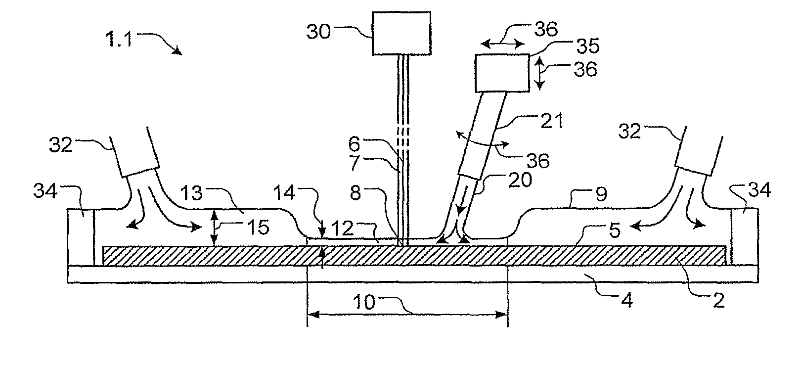
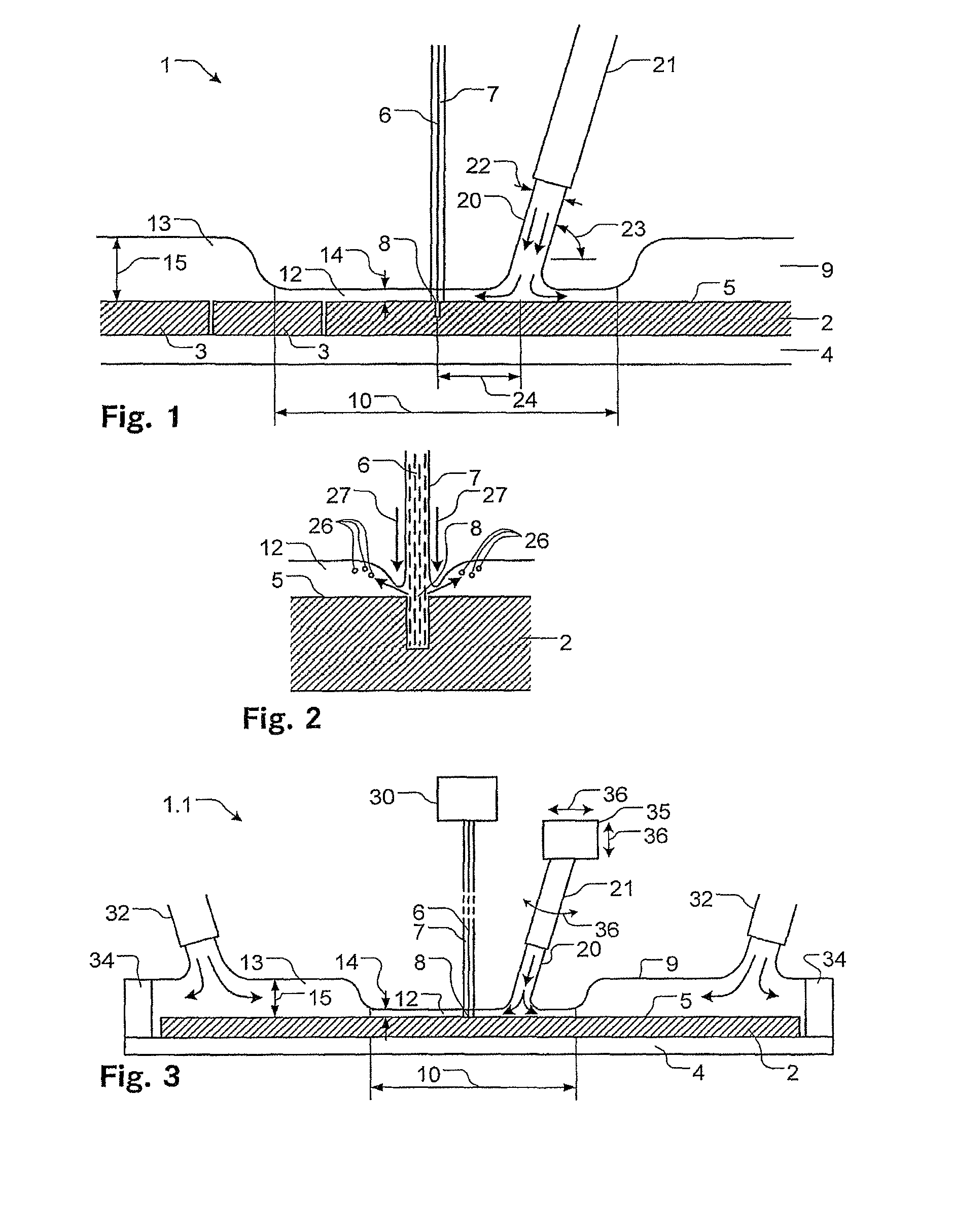
[0051]Identical parts are basically given the same reference symbols in the figures.

[0052]FIG. 1 shows a diagrammatic illustration of part of a device 1 according to the invention for machining a workpiece, a wafer 2 in the present example. The wafer is a silicon disk on which a multiplicity of integrated circuits are produced in a known way. The machining of the wafer 2, then, involves cutting the circuits, also called chips 3, out of the wafer 2. Wafers of this kind are, as a rule, round and have a diameter of the order of a few dozen to a few hundred millimeters and a thickness in the range of a few dozen to a few hundred micrometers.

[0053]The wafer 2 is fastened on a carrier 4. The wafer 2 is held on the carrier 4, above and below the latter, for example by means of a pressure difference. For example, the ambient or atmospheric pressure prevails above the carrier 4. Below the carrier 4, a greater or lesser vacuum is generated. Since the carrier 4 itself is made air-permeable, fo...


PUM

PropertyMeasurementUnit
thicknessaaaaaaaaaa
thicknessaaaaaaaaaa
thicknessaaaaaaaaaa

Abstract

The invention relates to a device (1) for cutting wafers (2) into a number of chips with a laser beam (6) injected into a liquid jet (7). A thin flowing liquid layer (9) having a blasting effect is produced on the surface (5) of the wafer (2). This makes it possible to prevent projections resulting during laser cutting from depositing once again on the surface of the wafer. The result is a very high cleanness of the surface after the cutting process. The liquid layer (9) is produced, in particular, so that it is thinner in a machining area (10) around the machining point (8) than outside of the machining area (10). This ensures that the liquid layer is sufficiently thin (14) at the machining point (8) so that enough laser energy for removing material is applied to the wafer surface, and ensures that the liquid layer is sufficiently thick (15) outside of the machining area so that no area of the surface (5) of the wafer (2) dries out.

Description

BACKGROUND OF THE INVENTION[0001]1. Field of the Invention[0002]The invention relates to a method for machining a workpiece by means of laser radiation injected and guided in a liquid jet, in which the liquid jet having the laser radiation is directed on to a surface of the workpiece and the workpiece is machined at an operating point. The invention relates, further, to a device for machining a workpiece by means of laser radiation which can be directed on to a surface of the workpiece, the workpiece being capable of being machined at an operating point, and the laser radiation being injected and guided in a liquid jet.[0003]2. Description of the Related Art[0004]Laser radiation can be used, particularly in industry, in many different ways for machining the most diverse possible materials, such as, for example, metals, plastics or even ceramics. Machining ranges from cutting, drilling and welding through to material removal or marking.[0005]Typically, in the machining of a workpiece...

Claims


Application Information

Patent Timeline
Patent Type & Authority Patents(United States)
IPC IPC(8): B23K26/14H01L21/00
CPCB23K26/1417B23K26/146H01L21/02002B23K26/38B23K26/16B23K26/122
Inventor RICHERZHAGEN, BERNOLDSPIEGEL, AKOS
Owner SYNOVA SA
Why Eureka
Try Eureka