
Cache memory system having at least one user area and one system area wherein the user area(s) and the system area(s) are operated in two different replacement procedures

a cache memory and user area technology, applied in the field of cache memory, can solve the problem of many conventional cache memories being expensiv

Inactive Publication Date: 2001-01-30
MITSUBISHI ELECTRIC CORP
View PDF15 Cites 27 Cited by
  • Summary
  • Abstract
  • Description
  • Claims
  • Application Information

AI Technical Summary

Benefits of technology

According to a third aspect of the invention, there is provided a cache memory, which is adapted to be situated adjacent to a CPU, for storing part of data in a main memory to make the CPU quicker, the cache memory comprising: a register which is situated on a cache internal address data bus and in which address areas inhibiting any ejection of the data in the cache memory are stored; and a memory area in which the data in the main memory and a flag showing any inhibited ejection of the data, whereby an address area in the main memory is designated to inhibit any ejection of data.
With the second arrangement, since the second memory area in which data such as shared data, unlikely to be purged or likely to remain permanently, is connected to the cache internal address data bus independently of the first memory area in which user data is stored, it is possible to make the computer system quicker.
Thus since the data in the memory area is replaced by referring to access information, it is possible to minimize cache mistakes.
With the third arrangement, since a value indicating inhibited ejection of data may be set with the flag corresponding to the data stored in the memory area, then it is possible to inhibit ejection of data. If there is an ejection inhibit area, the start and end addresses of such a range is stored in the register. If there is no ejection inhibit area, an initial value which indicates no inhibit area has been specified is set in the register. Since a high-frequency-access program such as a system program is set to ejection inhibit so as to be permanent, it is possible to minimize cache mistakes.

Problems solved by technology

Many conventional cache memories are expensive and have hence been used in only a limited part of the computer system.

Method used


Image

  • Cache memory system having at least one user area and one system area wherein the user area(s) and the system area(s) are operated in two different replacement procedures
  • Cache memory system having at least one user area and one system area wherein the user area(s) and the system area(s) are operated in two different replacement procedures
  • Cache memory system having at least one user area and one system area wherein the user area(s) and the system area(s) are operated in two different replacement procedures

Examples


second embodiment

A second preferred embodiment of this invention will now be described with reference to the accompanying drawings.

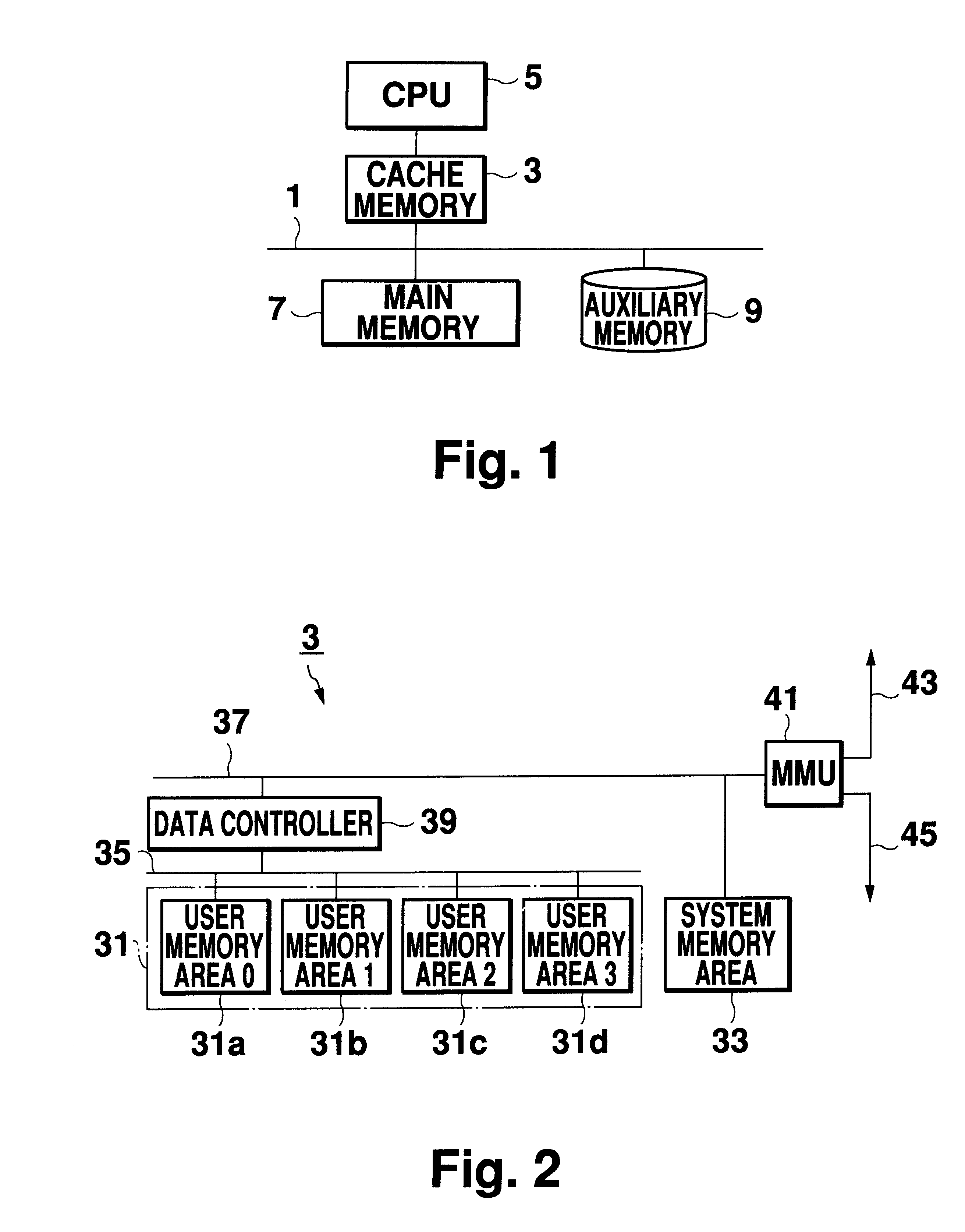
FIG. 1 is a block diagram showing the general structure of a computer system to which this embodiment is applied. As this computer system is similar in structure to that of the first embodiment, its description is omitted here for clarity.

FIG. 5 is a block diagram showing the structure of a cache memory 3. The parts or elements substantially similar to that of the first embodiment are designated by like reference numerals, and their description is omitted. A memory area 49 in which data in a main memory 7 is stored is connected to a cache internal address data bus 37 (hereinafter called "internal bus") via a data controller 47 equipped with an ejection inhibit area register in which the start and end addresses of an address area inhibiting ejection of data in the main memory 7 are stored. An memory management unit (hereinafter called "MMU") 41 of this embodiment issues a...


PUM


Abstract

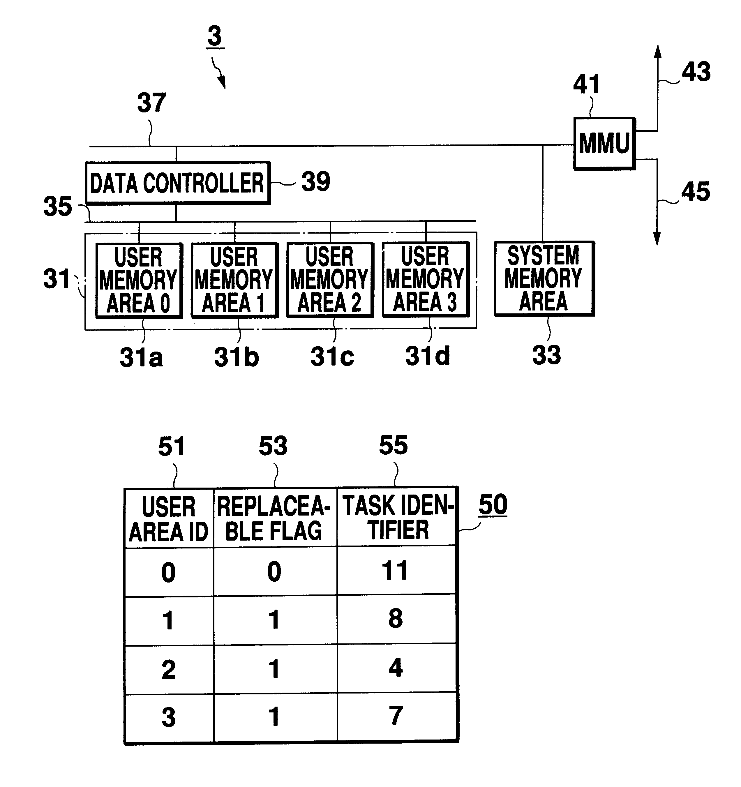
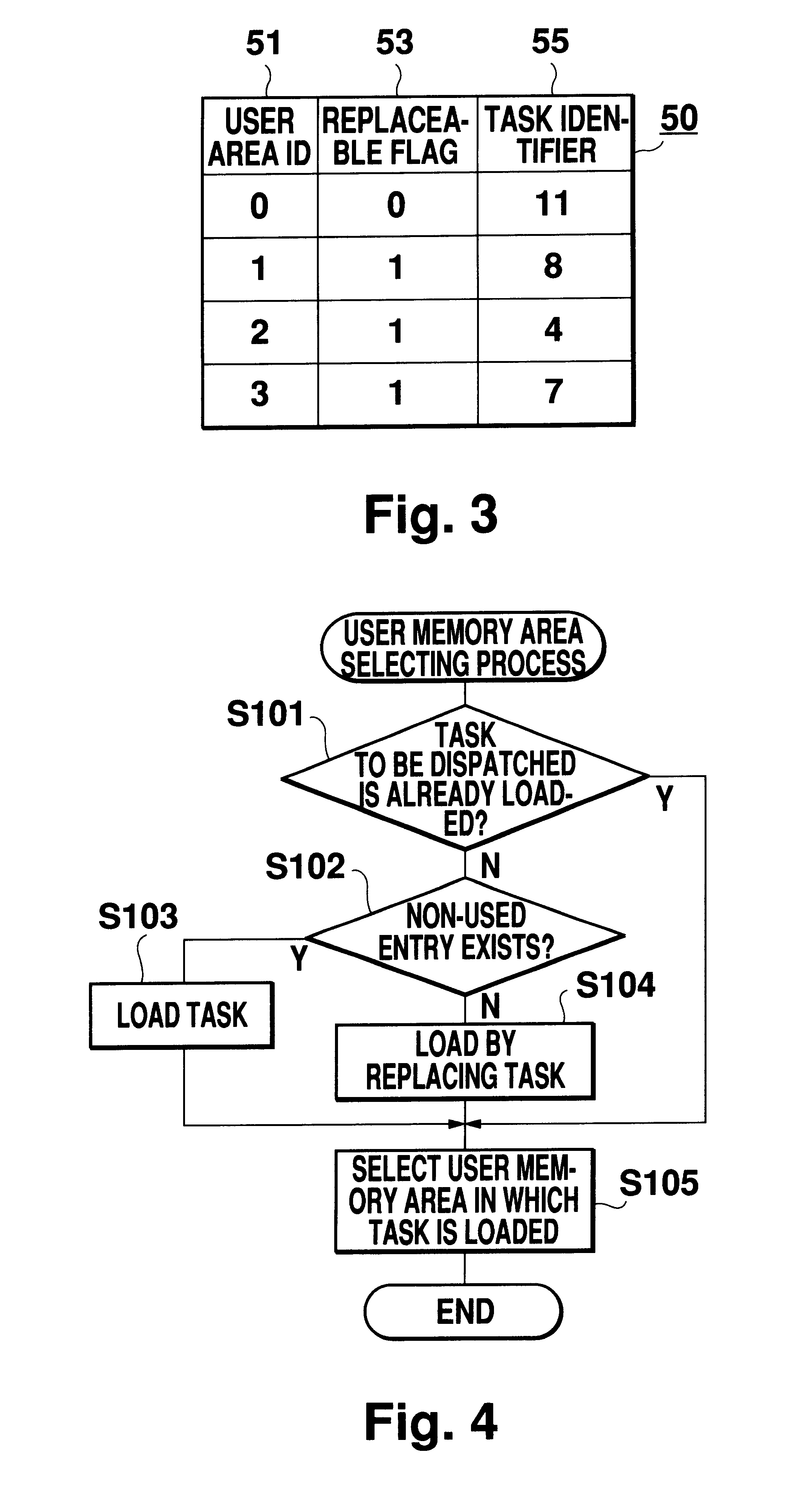
A cache memory having four user memory areas in which different data in a main memory is to be respectively stored, and a system memory area in which shared data between programs in the user memory areas is to be stored. A data controller has a route register in which address information, such as information as to whether or not the data in the respective user memory area is replaceable and task information, is to be stored. The individual user memory areas are connected to one another via a cache internal address data bus and a user-area cache internal sub-address data bus. The internal bus is connected to a CPU bus and a memory bus via a memory management unit for performing address translation, etc.

Description

1. Field of the InventionThis invention relates to a cache memory and more particularly to a cache memory which makes a computer system quicker by reducing cache misses.2. Description of the Related ArtMany conventional cache memories are expensive and have hence been used in only a limited part of the computer system. But as advances have been made in process technology, application of more inexpensive memories has been on the increase recently. Meanwhile the quicker the CPU, the higher the price which had to be paid for cache mistakes; consequently using cache memories would be a key to the performance of computer systems.The conventional technology for minimizing cache mistakes and making purge and load of data quicker is exemplified by the following prior art:Japanese Patent Laid-Open Publication No. SHO 60-79446 discloses a concept of putting a task identifier with data to be accessed in the cache memory only when a logical address to be accessed and the task identifier coincid...

Claims


Application Information

Patent Timeline
Patent Type & Authority Patents(United States)
IPC IPC(8): G06F12/12G06F12/08
CPCG06F12/0802G06F12/126
Inventor UEMURA, JOSESAKAKURA, TAKASHI
Owner MITSUBISHI ELECTRIC CORP
Learn More