Quick ice-making control method of ice-maker for refrigerator

a technology of ice-making control and refrigerator, which is applied in the direction of ice production, domestic cooling apparatus, lighting and heating apparatus, etc., can solve the problems of elongated time taken to make ice from water, disadvantageous ice-making control method of refrigerator ice-making control, etc., and achieve the effect of rapid making ice from water and promoting thermal transmission to water

Inactive Publication Date: 2006-03-28
LG ELECTRONICS INC
View PDF16 Cites 52 Cited by
  • Summary
  • Abstract
  • Description
  • Claims
  • Application Information

AI Technical Summary

Benefits of technology

[0031]Therefore, the present invention has been made in view of the above problems, and it is an object of the present invention to provide a quick ice-making control method of an ice-maker for a refrigerator, in which supplied water is stirred with an ejector for exhausting ice cubes so as to promote thermal transmission to the water, thereby quickly making ice from the water.

Problems solved by technology

Since the water supplied to the ice-maker mold 22 is cooled only by natural convection with the cool air in the freezing chamber (F) and the thermal conduction of the ice-maker mold 22, the above-described conventional ice-making control method of the ice-maker for the refrigerator is disadvantageous in that a time taken to make ice from the water is elongated.

Method used


Image

  • Quick ice-making control method of ice-maker for refrigerator
  • Quick ice-making control method of ice-maker for refrigerator
  • Quick ice-making control method of ice-maker for refrigerator

Examples


first embodiment

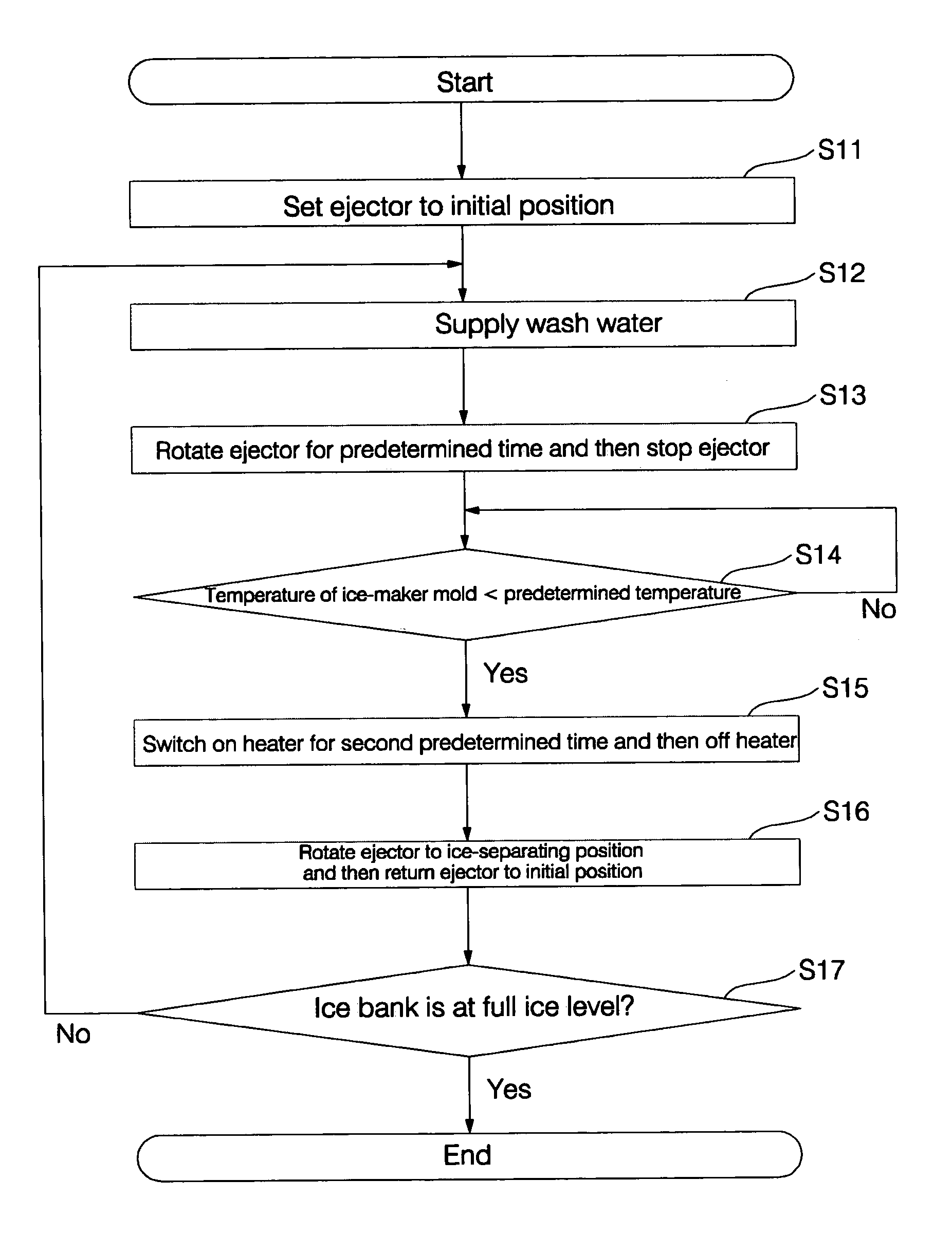
[0095]FIG. 13 is a flow chart illustrating a quick ice-making control method of the ice-maker for the refrigerator in accordance with the present invention.

[0096]First, when power is inputted to the refrigerator, the ice-making controller 68 controls the motor 65 to set the ejector 64 to an initial position (A) (S11).

[0097]The ice-making controller 68 switches on the water supply valve intermitting the water supplied to the cup 61 for a designated time, and then switches off the water supply valve (S12).

[0098]The water supplied from the outside during the time taken to switch on the water supply valve is contained in the cup 61, and is then transferred into the ice-maker mold 62.

[0099]Thereafter, the water contained in the ice-maker mold 62 is heat-exchanged with cool air in the freezing chamber (F) or the ice-maker mold 62, thereby being cooled and gradually frozen from at a portion thereof contacting the cool air or the ice-maker mold 62.

[0100]The ice-making controller 68 rotates ...

second embodiment

[0123]FIG. 17 is a flow chart illustrating a quick ice-making control method of the ice-maker for the refrigerator in accordance with the present invention.

[0124]First, when power is inputted to the refrigerator, the ice-making controller 68 controls the motor 65 to set the ejector 64 to an initial position (A) (S31).

[0125]The ice-making controller 68 switches on the water supply valve (not shown) intermitting the water supplied to the cup 61 for a designated time, and then switches off the water supply valve (S32).

[0126]The water supplied from the outside during the time taken to switch on the water supply valve is contained in the cup 61, and is then transferred into the ice-maker mold 62.

[0127]Thereafter, the water contained in the ice-maker mold 62 is heat-exchanged with cool air in the freezing chamber (F) or the ice-maker mold 62, thereby being cooled and gradually frozen from at a portion thereof contacting the cool air or the ice-maker mold 62.

[0128]The ice-making controller...


PUM


Abstract

Disclosed is a quick ice-making control method of an ice-maker for a refrigerator, in which an ejector for extracting obtained ice stirs supplied water to be frozen so as to promote thermal transmission of the water. The quick ice-making control method includes the steps of (a) supplying water into an ice-maker mold, (b) quickly freezing the water by rotating an ejector for a predetermined time after the step (a), and (c) separating the obtained ice from the ice-maker mold in case that a temperature of the ice-maker mold is lower than a predetermined temperature after the step (b).

Description

BACKGROUND OF THE INVENTION[0001]1. Field of the Invention[0002]The present invention relates to a quick ice-making control method of an ice-maker for a refrigerator, and more particularly to a quick ice-making control method of an ice-maker for a refrigerator, in which water supplied to be made into ice cubes is stirred with an ejector for exhausting the ice cubes.[0003]2. Description of the Related Art[0004]Generally, refrigerators maintain a freezing chamber or a refrigerating chamber at a low temperature by means of a refrigerating cycle of a refrigerant.[0005]FIG. 1 is a perspective view of a conventional refrigerator.[0006]As shown in FIG. 1, the conventional refrigerator comprises a barrier 1 for dividing the inside of the refrigerator into a freezing chamber (F) and a refrigerating chamber (R), a main body 2 provided with a refrigerating cycle device for maintaining the freezing chamber (F) and the refrigerating chamber (R) at a low temperature, a freezing chamber door 4 rot...

Claims


Application Information

Patent Timeline
Patent Type & Authority Patents(United States)
IPC IPC(8): F25C5/08F25C1/24F25C1/04F25C1/20F25C5/18
CPCF25C1/04F25C1/20F25D2400/30F25C2500/02F25C2500/06F25C2400/10F25C2305/024F25C1/24
Inventor LEE, MYUNG RYULKIM, SEONG JAE
Owner LG ELECTRONICS INC
Why Eureka
Try Eureka