Positive airway pressure device

a positive airway and pressure device technology, applied in the direction of valves, mechanical devices, operating means/releasing devices, etc., can solve the problems of reducing the size of water containers, reducing the efficiency of pap devices, and reducing so as to reduce the noise produced by pap devices and reduce the possibility of leakage

Active Publication Date: 2010-06-03
RESMED LTD
View PDF13 Cites 57 Cited by
  • Summary
  • Abstract
  • Description
  • Claims
  • Application Information

AI Technical Summary

Benefits of technology

[0014]An even further aspect of the invention relates to a PAP device that improves heat conduction to the flow of air, a supply of water that humidifies the air, and / or the humidified air flow.
[0016]Still another aspect of the invention relates to a PAP device that reduces the noise produced by operation of the PAP device.
[0017]Another aspect of the invention relates to a PAP device that may comprise a humidifier configured to store a supply of water to humidify the flow of air and that has a reduced possibility of leakage.
[0020]A further aspect of the invention relates to a PAP device that includes a power supply and control to supply power and control to a flow generator configured to generate the flow of breathable gas and / or a heating element that is configured to heat the flow of breathable gas and / or a supply of water to humidify the flow in which the power supply and control and / or heating element is at less risk of water leaking into the power supply and control and / or the heating element.

Problems solved by technology

However, in seeking to reduce the size of the CPAP machines there has been a trade-off between reduced size on the one hand and reduced performance on the other.
Reducing the size of CPAP machines, including humidifiers, has led to a decrease in the size of water containers making it more difficult to provide humidification of the air supply during the entirety of the patient's sleep cycle.
This creates problems in maintaining a sufficient moisture pickup.
The integration of humidifiers with flow generators also makes it more difficult to clean the water container of the humidifier due to complex shapes of the tub and cover.
Humidifiers which are attachable to the flow generator also suffer from certain drawbacks.
In some instances, the humidifier increases the size of the footprint of the device, meaning a table or stand may no longer be of suitable size to hold the device once the humidifier is attached.
Some humidifiers also have seals that are submerged and that may tend to deteriorate over time with prolonged contact to water, increasing the propensity for leaks.
The metal in these plates may corrode over time, reducing the effectiveness, even destroying, the humidifier.
The heat in the PAP device itself may often build up and reduce bearing life within the device.

Method used


Image

  • Positive airway pressure device
  • Positive airway pressure device
  • Positive airway pressure device

Examples


first embodiment

PAP Device First Embodiment

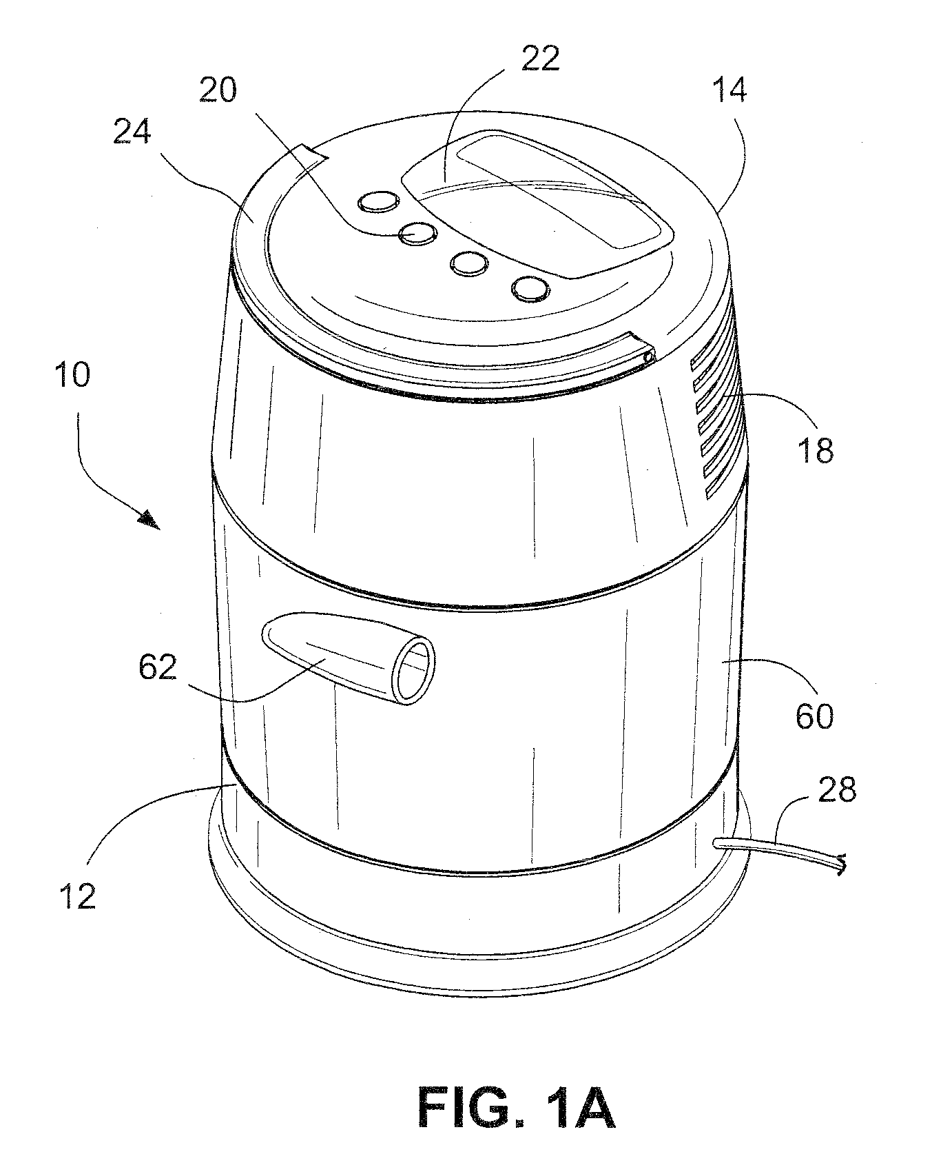
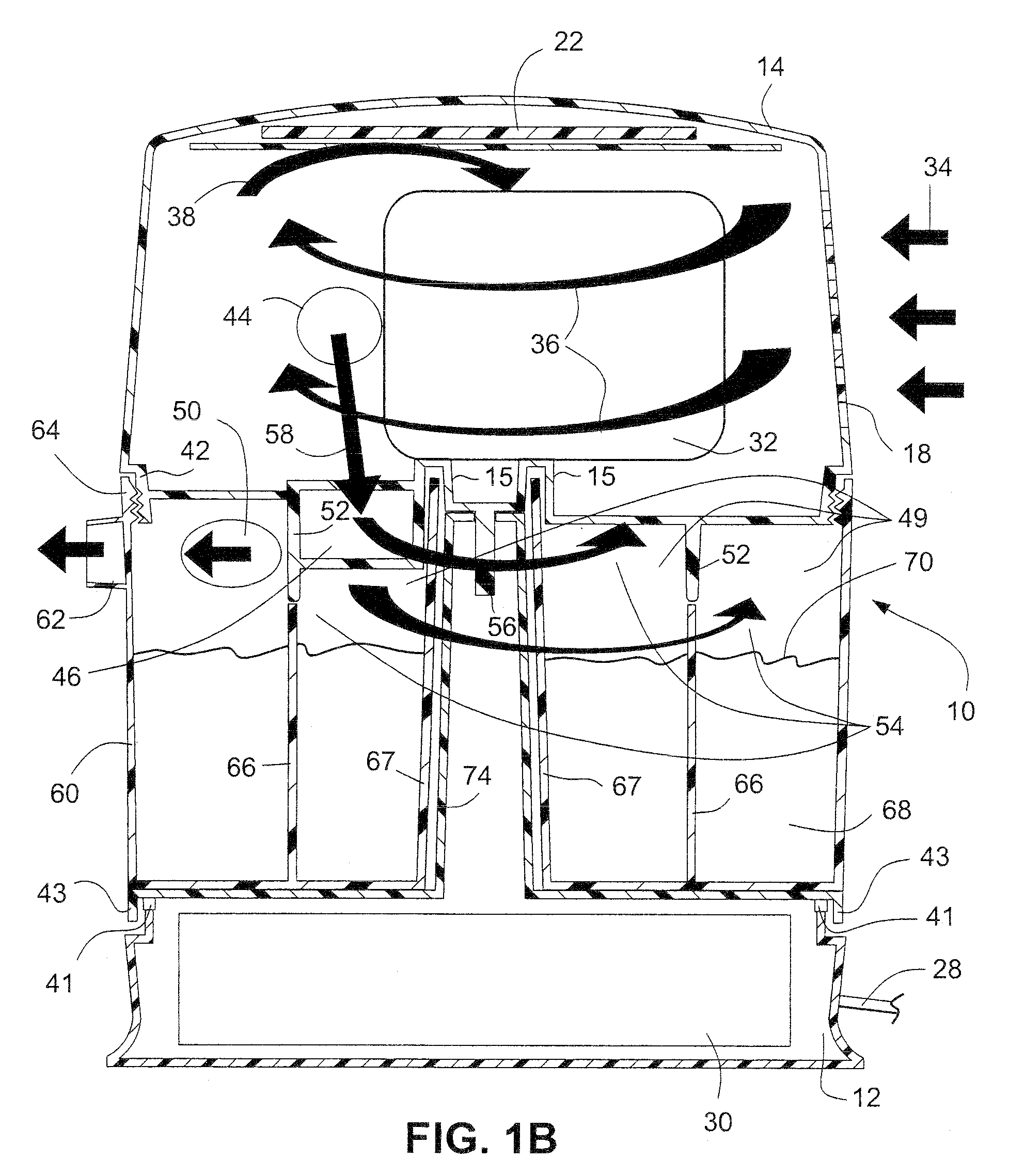
[0041]Referring to FIGS. 1A and 1B, a PAP device 10 according to a sample embodiment may comprise a flow generator provided in a flow generator housing 14 and a humidifier 60 configured to contain a supply of water to humidify the flow of breathable gas generated by the flow generator. The humidifier 60 comprises an outlet 62 that is tangentially provided on the outer surface. The PAP device 10 may be configured to be portable and include a handle 24 provided to the flow generator housing part 14. The PAP device 10 may be sized to be carried around by the handle 24, or in a small container, such as a tote bag.

[0042]The PAP device 10 comprises a power base 12 that is configured to house a power supply and control unit 30. The power base 12 may include an electrical connector 28, for example an electrical cord configured to deliver AC current to the power supply and control unit 30 of the PAP device 10. It should be appreciated that the power supply and cont...

second embodiment

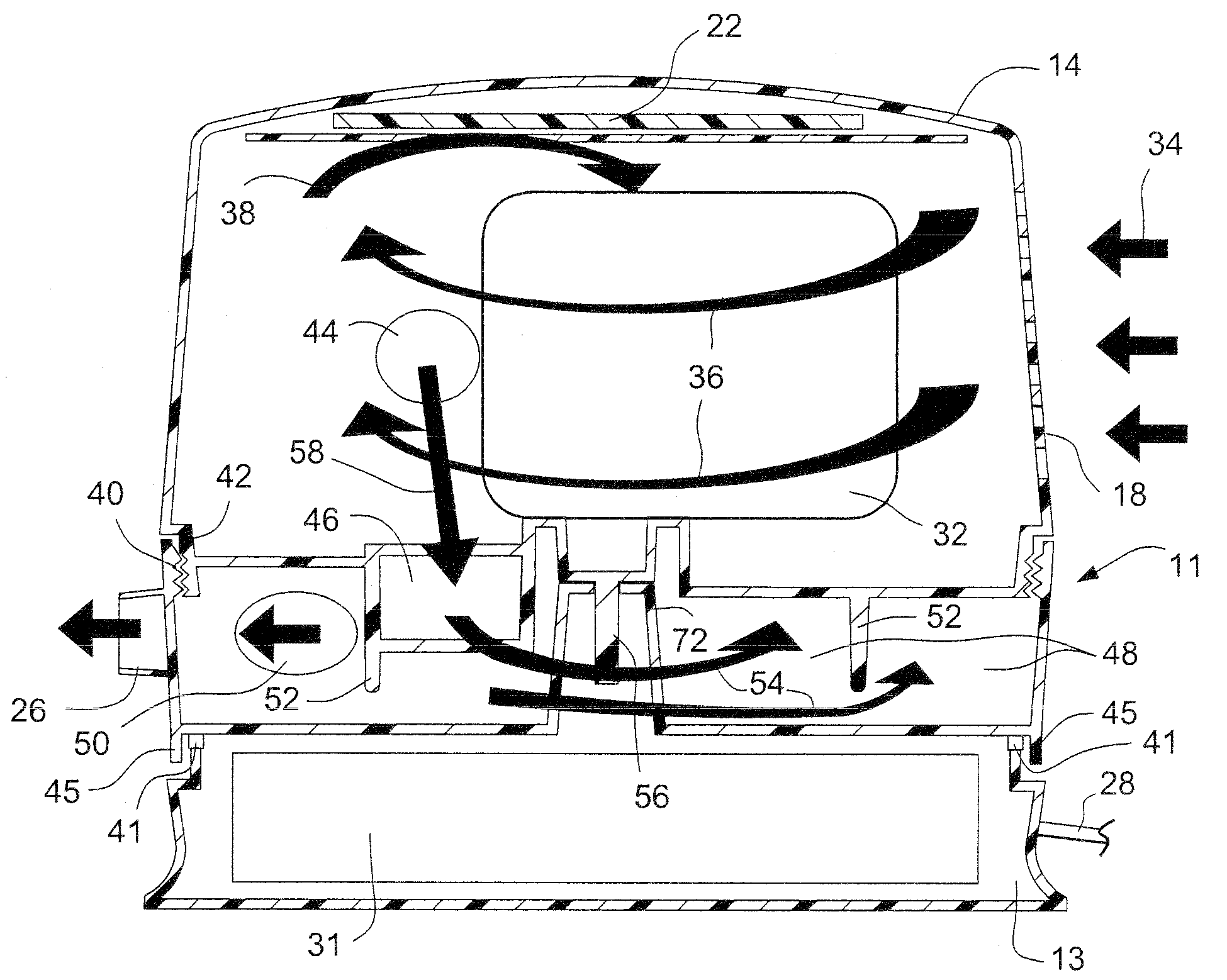
PAP Device Second Embodiment

[0054]Referring to FIGS. 3, 4A and 4B, a PAP device 11 according to another sample embodiment of the invention may comprise a power base 13 and the flow generator housing 14. The power base 13 houses a power supply and control unit 31. As shown in FIG. 4A, the flow generator housing 14 includes the threaded portion 42 that is threadably connectable to a threaded portion 40 of the power base 13. It should be appreciated that the flow generator housing 14 and the power base 13 may be connected by other mechanisms, for example a hinge. The flow generator housing 14 may be connected to the power base 13 by the connector 56 and a connector 72. The connectors 56, 72 may be, for example, circular multipole connectors. The power base 13 may include cooling vents 41 that are protected by a lip 45. The power base 13 may be sealed rather than vented.

[0055]One or more baffles or mufflers may be provided within the first housing part 14 to reduce the sound of the PAP ...

third embodiment

PAP Device Third Embodiment

[0059]Referring to FIGS. 6-8, a PAP device 10 comprises a flow generator 86 and a humidifier 96. The flow generator 86 is configured to generate a flow of breathable gas, e.g. air, and includes a blower motor assembly 98 provided in a blower motor assembly housing 100. The blower motor assembly 98 may comprise at least one impeller that is rotatably driven by a motor. A blower motor assembly suitable for use in the embodiment shown in FIG. 6 is disclosed in, for example, WO 2007 / 134405 A1 and U.S. Patent Application Publication 2008 / 0304986 A1, the entire contents of both being incorporated herein by reference. The blower motor assembly 98 may be connected to an electrical connection 28, for example an electrical cord configured to be inserted into an AC outlet.

[0060]The blower motor assembly housing 100 may define a chamber 104 that is configured to house the blower motor 98 and a heater element 102, for example a heater plate. The chamber 104 may he form...


PUM


Abstract

A positive airway pressure (PAP) device for supplying a flow of breathable gas to a patient includes a first housing; a flow generator provided in the first housing, the flow generator configured to generate a flow of breathable gas; a second housing configured to be connected to the first housing, the second housing including a channel having an inlet configured to receive the flow of breathable gas and an outlet configured to discharge the flow of breathable gas, wherein the first housing is provided on top of the second housing such that a footprint of the PAP device is not substantially increased beyond a footprint of the second housing.

Description

CROSS REFERENCE TO RELATED APPLICATION[0001]This application claims priority to U.S. Application 61 / 113,715, filed Nov. 12, 2008, the entire contents of which are incorporated herein by reference.FIELD OF THE INVENTION[0002]The present invention relates to positive airway pressure devices for respiratory therapy for treating, for example, Sleep Disordered Breathing (SDB). The present invention also relates to components for positive pressure airway devices.BACKGROUND OF THE INVENTION[0003]Positive Airway Pressure (PAP), including Continuous Positive Airway Pressure (CPAP), is a form of Noninvasive Positive Pressure Ventilation (NIPPV) for the treatment of Osbtructive Sleep Apnea (OSA). PAP treatment involves the delivery of a pressurized breathable gas, usually air, to a patient's airways using a conduit and a patient interface, for example, a mask. Gas pressures employed for CPAP treatment typically range from 4 cm H2O to 20 cm H2O, at flow rates of up to 180 l / min (measured at the...

Claims


Application Information

Patent Timeline
Patent Type & Authority Applications(United States)
IPC IPC(8): A61M16/00
CPCA61M16/0066A61M16/16A61M2205/3653A61M2205/3666A61M2205/42A61M2205/502A61M16/108A61M2205/8206A61M2205/8262A61M16/06A61M16/0875A61M16/1075A61M2205/6081A61M16/0069A61M16/0816A61M2016/003A61M2205/3334A61M2205/3368A61M16/0003A61M16/109
Inventor MARTIN, DION CHARLES CHEWEKENYON, BARTON JOHNVIRR, ALEXANDERDOUDKINE, DMITRI ANATOLIEVICHKWOK, PHILIP RODNEYNAPPER, RICHARD CHARLESSNOW, JOHN MICHAEL
Owner RESMED LTD
Why Eureka
Try Eureka