Large scale display system

a display system and large-scale technology, applied in the field of large-scale display systems, can solve the problems of reducing the screen size of known systems, reducing the display system's size, so as to achieve the effect of reducing or reducing to a certain amoun

Inactive Publication Date: 2009-05-21
LAADTECH
View PDF8 Cites 54 Cited by
  • Summary
  • Abstract
  • Description
  • Claims
  • Application Information

AI Technical Summary

Benefits of technology

[0008]It is an object of this invention to provide a large scale display system which alleviates or reduces to a certain level one or more of the above disadvantages.

Problems solved by technology

The known display systems are therefore relatively heavy and bulky.
As such, they are costly to transport and to assemble.
These known systems are limited to a screen size of about 120m2 due to structural and transportation limitations.
Invariably, there would be damage to the facade of the building.
They are not flexible as they are not easily customised for a different screen size, nor can they be shaped into a non rectangular planar screen.
Being rigid, they cannot be transformed to a curved screen.
Due to the high costs of transportation and assembly of the known display systems, they are uneconomical for short term use, such as during festive occasions, Christmas and New Years for example.
Accordingly, those system require a large number of wires and electrical connectors, which further add to their costs and weight.
The number of wires and connections also result in a relatively long assembly time.
In full sunlight, the images formed by the LEDs are almost not viewable outdoor due to bright natural light.
When not operating, the prior art systems seems like a dark rectangle and are not aesthetic.

Method used


Image

  • Large scale display system
  • Large scale display system
  • Large scale display system

Examples


Embodiment Construction

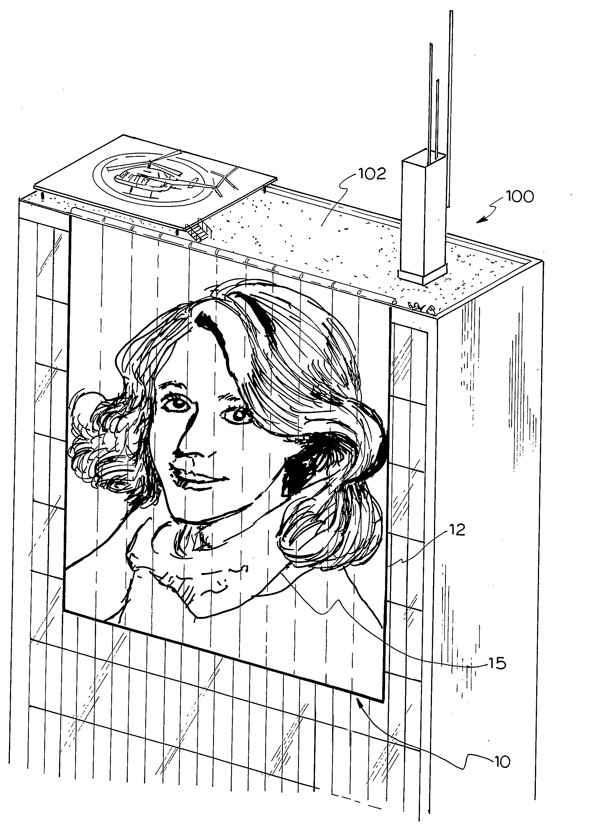
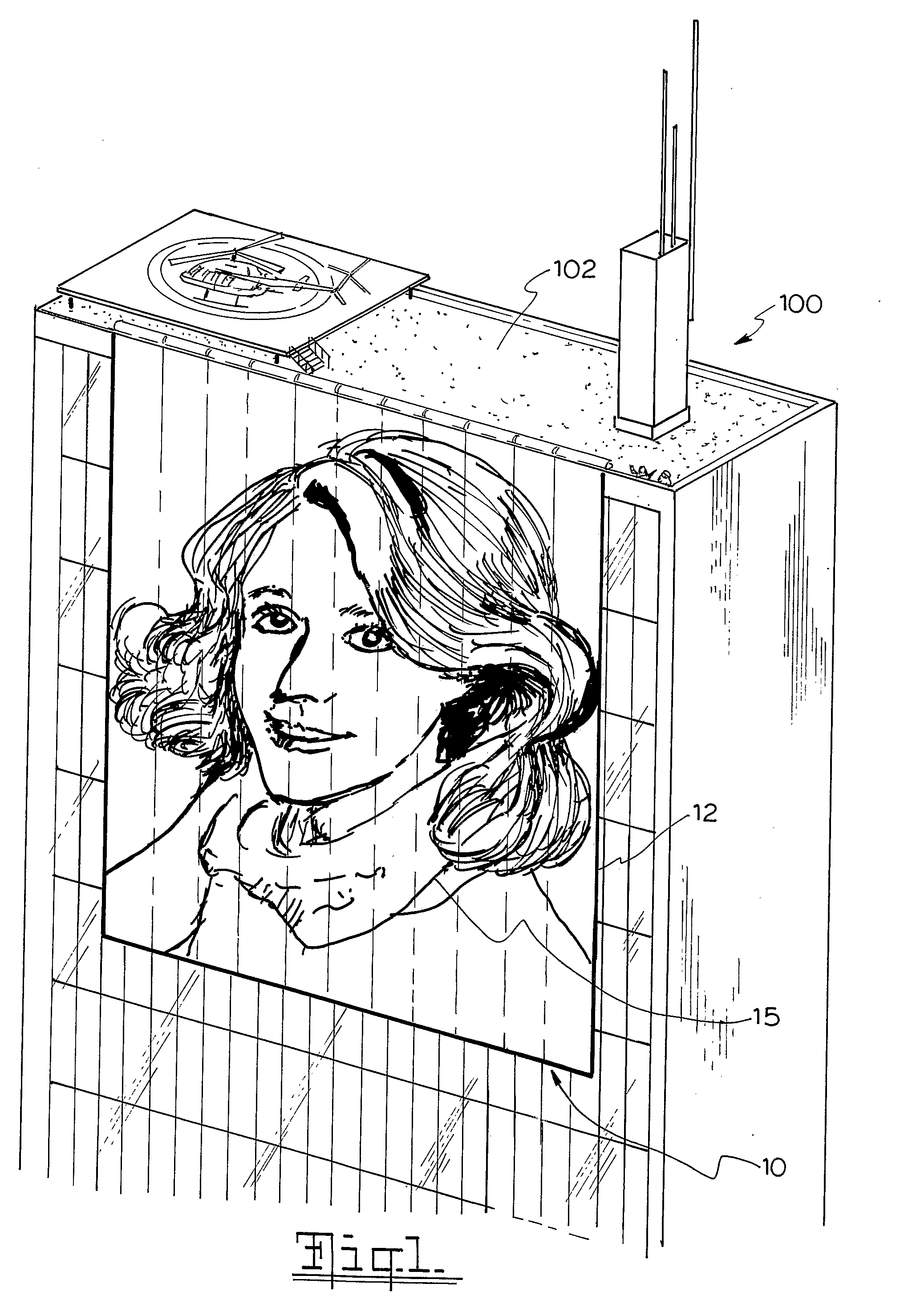
[0072]Referring to the drawings and initially to FIG. 1 there is shown an embodiment of the large scale LED display system 10 according to the present invention. The display system 10 is supported on a multistory building 100, and it extends over a substantial part of an external surface of the building 100. As shown, the display system 10 is supported on the roof 102 and extends downward over multiple levels of the building 100.

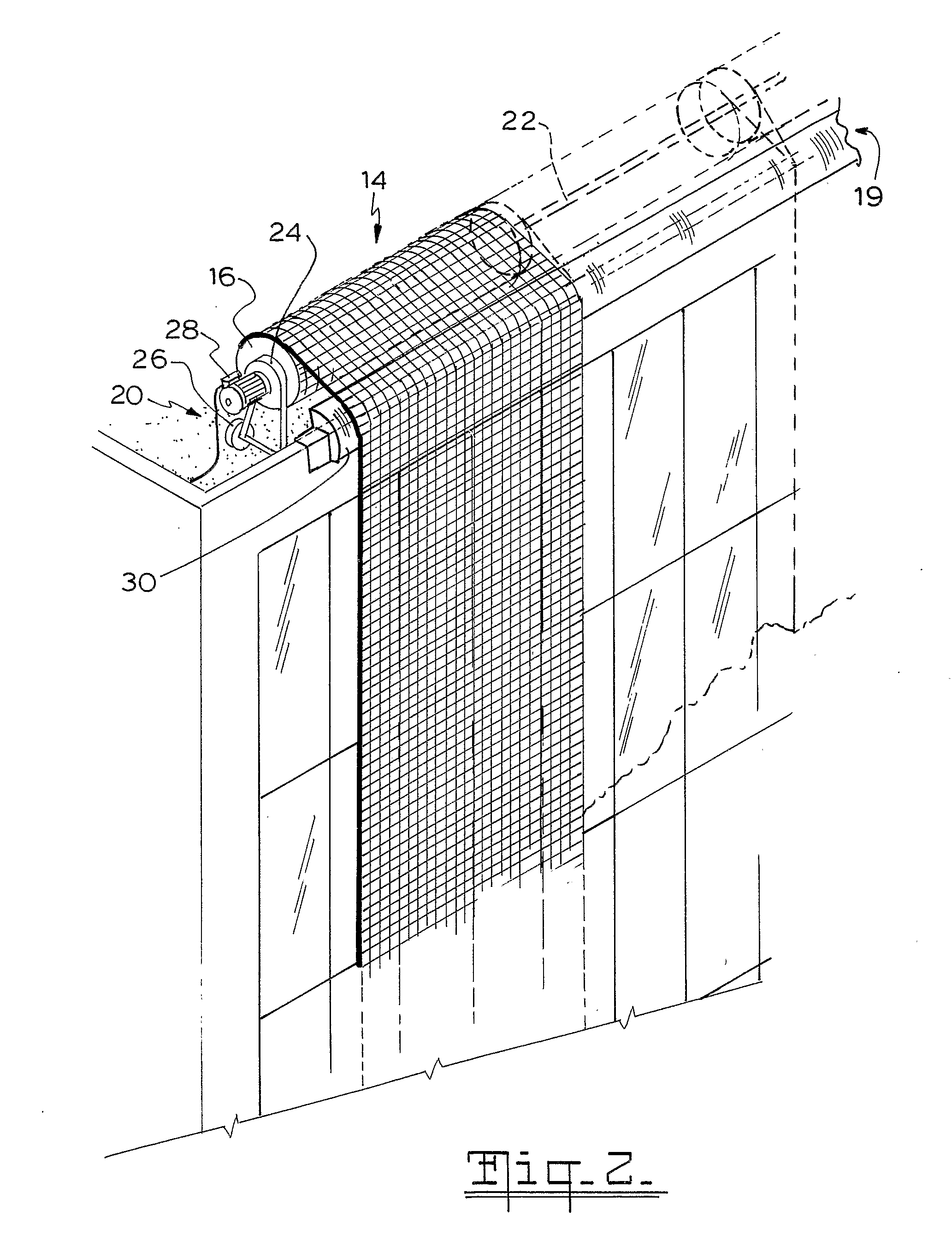
[0073]The display system 10 has a display screen 12 formed of a number of interconnected side by side display panels 14 (see FIG. 2). Each of the panels 14 can be rolled about a drum roll 16 during storage or for transportation. The rolled display panels can thus be easily moved from one location to another location. FIG. 3 shows one display panel 14 secured to a wheeled hand trolley 18 that is wheeled by a worker, as one example of transportation. Referring again to FIG. 2, the display panels 14 are supported by a suspension arrangement 19. The suspension a...


PUM


Abstract

A large scale LED display system (12) is provided on a building structure (100). The system has a screen (12) formed of a number of side by side display panels (14) which may be foldable or rollable. Each panel has a number of equally spaced transparent polycarbonate tubes (80) which house pixel units (50) of LEDs (51) connected to printed circuit board (120) and a row controller (121) for controlling luminance of the LEDs. A bus member (54) convey power and video control signals from a panel controller (77) to each row controller. The panel controller has an initialising process adapted to allocate temporary addresses for the tubes and determine screen size accordingly. Video segments are extracted by the row controllers based on the addresses associated with the video control signals from the panel controller.

Description

BACKGROUND OF THE INVENTION[0001]Large scale display systems are used to display live television broadcast events such as a game of sports or a stage entertainment performance, advertising and promotional materials, greetings at festive times, etc. Generally, light emitting diodes (LED) are arranged to form pixels which are controllable to provide images in a full range of visible colours. The display systems known to the applicant are formed of rigid display boards that are mechanically and electrically connected together. The connected boards are then supported on a rigid and sturdy support structure. The display boards must be mechanically and electrically connected together as a unit. The known display systems are therefore relatively heavy and bulky. As such, they are costly to transport and to assemble. These known systems are limited to a screen size of about 120m2 due to structural and transportation limitations.[0002]To support the known display system on a building, the sy...

Claims


Application Information

Patent Timeline
Patent Type & Authority Applications(United States)
IPC IPC(8): G09G3/34
CPCG06F3/1446G09F9/33G09F19/226G09G3/32G09F19/22
Inventor GELDARD, WILLIAM SCOTTINGLIS, PETERMENZIES, SCOTT ANDREWXAVIER, DOMINIC MICHAEL
Owner LAADTECH
Why Eureka
Try Eureka