
Accurately predicting and preventing interference between tooth models

a technology of accurate prediction and prevention, applied in the field of dental care, can solve the problems of manually applying such bends, humanly impossible to accurately estimate three-dimensional wire bends, and inability to accurately develop visual three-dimensional images of orthodontic structures, etc., to prevent interference between adjacent tooth models, reduce cost, and eliminate the cost of multiple tooth arch models in orthodontic treatment

Active Publication Date: 2007-11-13
ALIGN TECH
View PDF2 Cites 94 Cited by
  • Summary
  • Abstract
  • Description
  • Claims
  • Application Information

AI Technical Summary

Benefits of technology

[0041]Embodiments may include one or more of the following advantages. An advantage of the present invention is that adjacent physical tooth models in a physical dental arch model can be simulated. The interference between the two physical models can be predicted before they are assembled to form a physical arch model. The positions and the orientations of the tooth models can be adjusted to prevent the interference. As a result, the precision and effectiveness of the orthodontic treatments are improved.
[0042]Another advantage of the present invention is that the physical tooth models can be used to form different tooth arch models having different teeth configurations. The pin configurations can be modified without changing the tooth models themselves to be modified to prevent interference between adjacent tooth models at different steps of an orthodontic treatment. Moreover, the tooth models can be reused as tooth positions are changed during a treatment process. Much of the cost of making multiple tooth arch models in orthodontic treatment are therefore eliminated. The tooth models can have pins that assist their assembling with a base.
[0043]Another advantage of the present invention is that the same base can support different tooth arch models having different teeth configurations. The base can include more than one sets of receiving features that can receive tooth models at different positions. The reusable base further reduces cost in the dental treatment of teeth alignment. Furthermore, the receiving features can be modified to receive tooth models having different pin configurations to avoid interference between the adjacent tooth models in a tooth arch model.
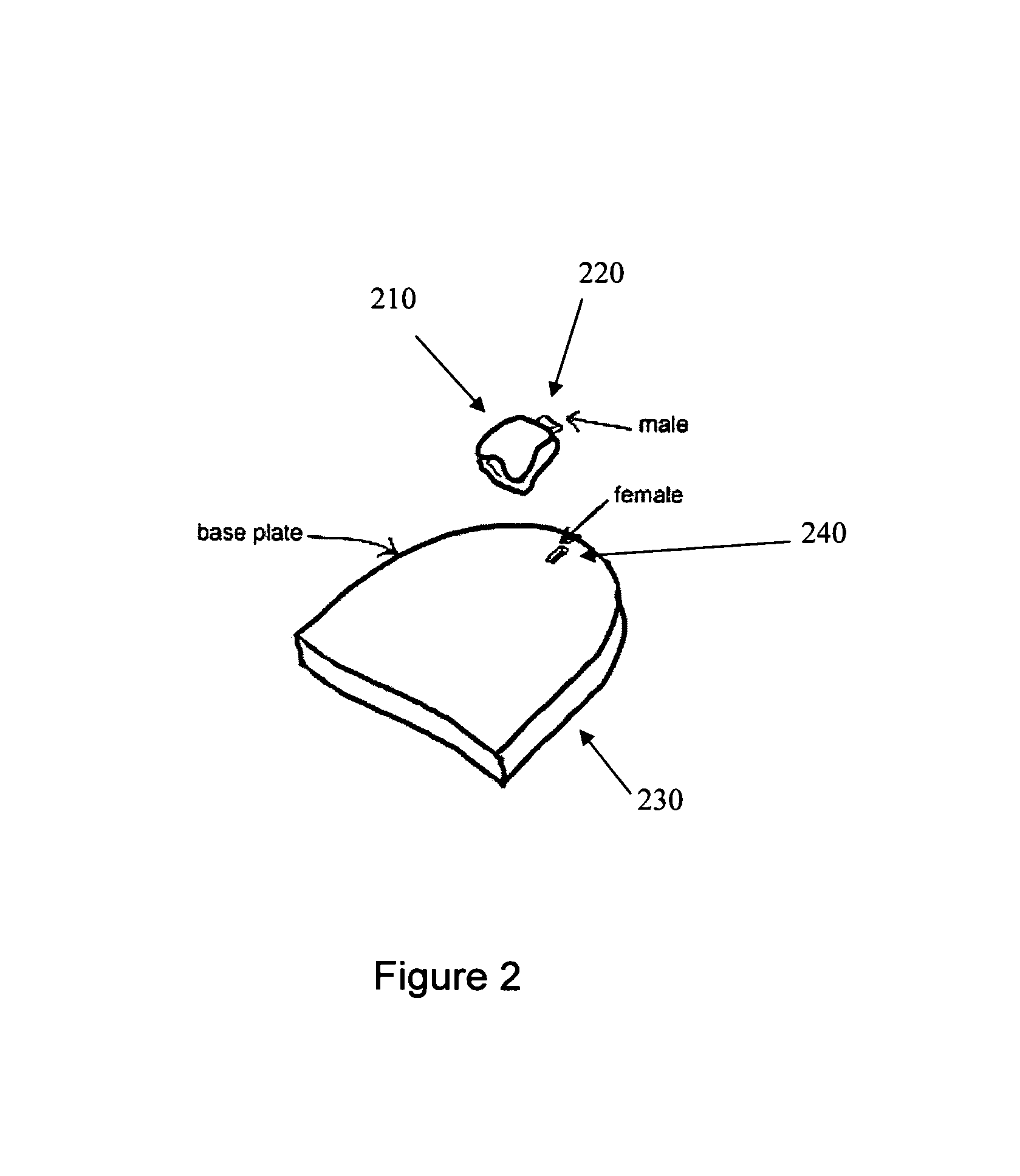
[0044]The physical tooth models include features to allow them to be attached, plugged or locked to a base. The physical tooth models can be pre-fabricated having standard registration and attaching features for assembling. The physical tooth models can be automatically assembled onto a base by a robotic arm under computer control.
[0045]The physical dental arch model obtained by the disclosed system and methods can be used for various dental applications such as dental crown, dental bridge, aligner fabrication, biometrics, and teeth whitening. The arch model can be assembled from segmented manufacturable components that can be individually manufactured by automated, precise numerical manufacturing techniques.
[0046]The physical tooth models in the physical dental arch model can be easily separated, repaired or replaced, and reassembled after the assembly without the replacement of the whole arch model. The manufacturable components can be attached to a base. The assembled physical dental arch model specifically corresponds to the patient's arch. There is no need for complex and costly mechanisms such as micro-actuators for adjusting multiple degrees of freedom for each tooth model. The described methods and system is simple to make and easy to use.

Problems solved by technology

Unfortunately, in the oral environment, it is impossible for a human being to accurately develop a visual three-dimensional image of an orthodontic structure due to the limitations of human sight and the physical structure of a human mouth.
In addition, it is humanly impossible to accurately estimate three-dimensional wire bends (with an accuracy within a few degrees) and to manually apply such bends to a wire.
Further, it is humanly impossible to determine an ideal bracket location to achieve the desired orthodontic structure based on the mental images.
It is also extremely difficult to manually place brackets in what is estimated to be the ideal location.
As a result of multiple wire changes, patient discomfort is increased as well as the cost.
That is, when an appliance is first worn by the patient, certain of the teeth will be misaligned relative to an undeformed geometry of the appliance cavity.
Several drawbacks exist however with the stereo lithography process.
The materials used by stereo lithography process may be toxic and harmful to human health.
Furthermore, stereo lithography process used by Align Technology also requires a different aligner mold at each stage of the treatment, which produces waste and is environmental unfriendly.
Making a model for a whole or a large portion of an arch is much more difficult than making one tooth abutment for implant purposes.
Some prior art making the physical dental arch model is carried out manually, involving not only a substantial amount of labor required, but also a substantial amount of time.
It is also extremely difficult to machine an accurate arch model because of the various complex shapes and the complex features such as inter-proximal areas, wedges between teeth, etc. in an arch.

Method used


Image

  • Accurately predicting and preventing interference between tooth models
  • Accurately predicting and preventing interference between tooth models
  • Accurately predicting and preventing interference between tooth models

Examples


Embodiment Construction

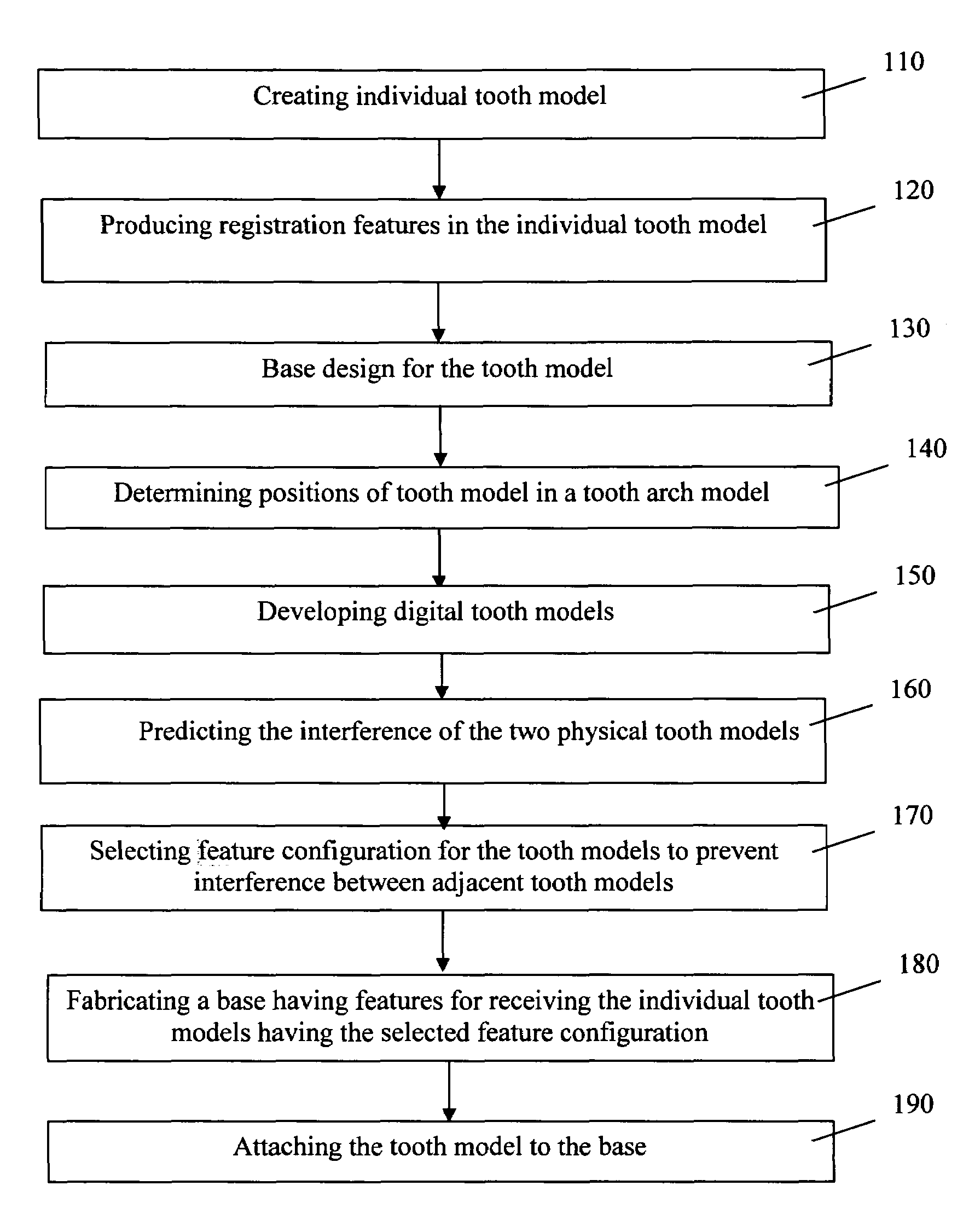
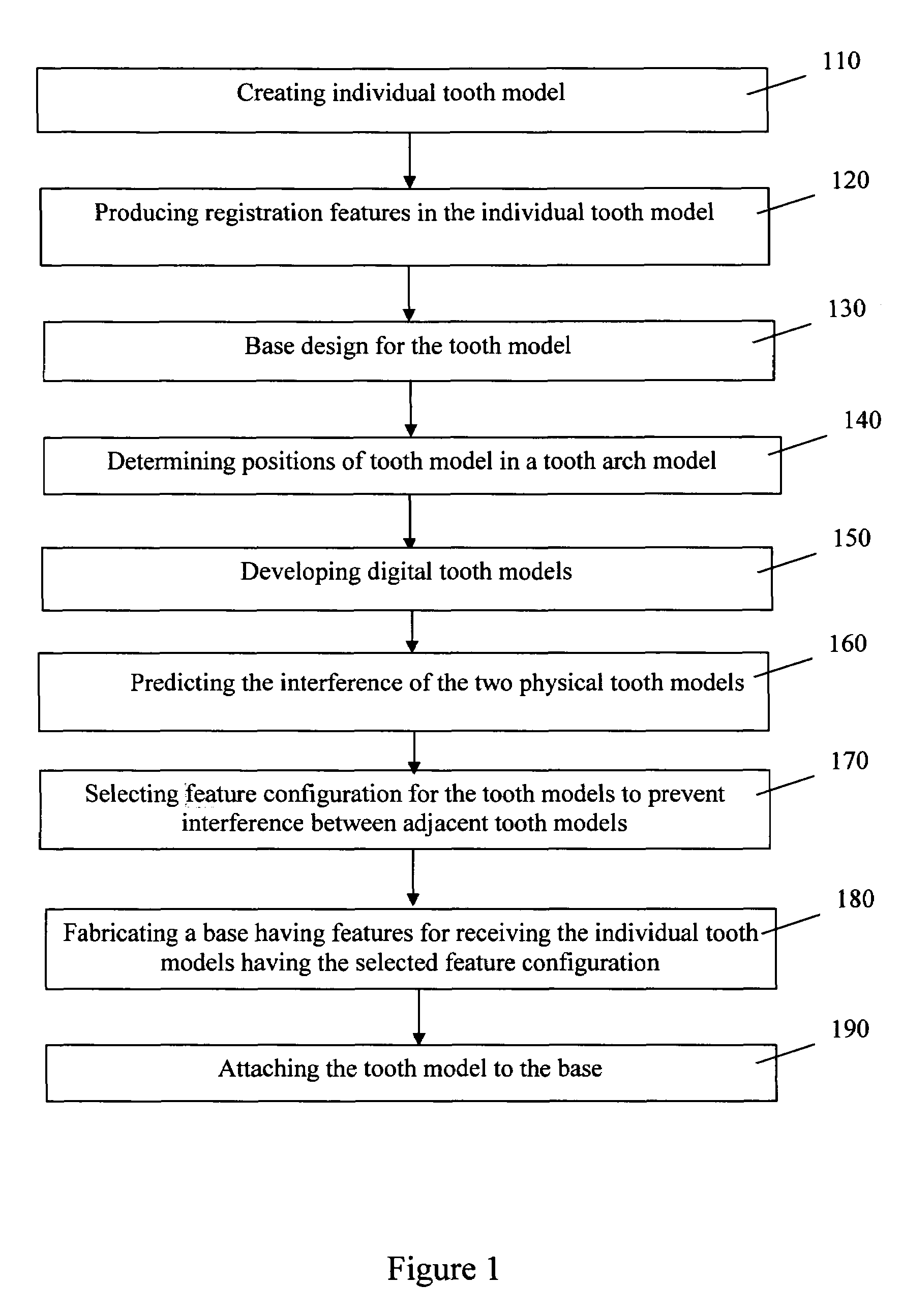
[0076]Major operations in producing a physical dental arch model are illustrated in FIG. 1. The process generally includes the following steps. First individual tooth model is created in step 110. An individual tooth model is a physical model that can be part of a physical tooth arch model, which can be used in various dental applications. Registration features are next added to the individual tooth model to allow them to be attached to each other or a base in step 120. A base is designed for receiving the tooth model in step 130. The tooth model positions in a tooth arch model are next determined in step 140. The digital tooth models are developed in step 150. The interference between the physical tooth models is predicted in step 160. In step 170, the pin configurations affixed to the tooth models are selected to prevent interference between adjacent tooth models when they are mounted on the base. A base is fabricated in step 180. The base includes features for receiving the indiv...


PUM


Abstract

Systems and methods for preventing interference between two physical tooth models in a physical dental arch model includes digitally representing the surfaces of each of the two physical tooth models by a mesh of points in three dimensions, interpolating the meshes of points to produce interpolated surfaces to represent the boundaries of the two physical tooth models, wherein the interpolated surfaces representing the boundaries of the two physical tooth models intersect at least at one point to form an overlapping portion. The method also includes specifying a straight line running through the overlapping portion and intersecting the two interpolated surfaces representing the boundaries of the two physical tooth models and calculating the length of the straight line in the overlapping portion to quantify the interference between the two physical tooth models.

Description

CROSS-REFERENCES TO RELATED INVENTIONS[0001]The present invention is also related to commonly assigned U.S. Patent Application, titled “A base for physical dental arch model” by Huafeng Wen, filed November 2004, commonly assigned U.S. Patent Application, titled “Accurately producing a base for physical dental arch model” by Huafeng Wen, filed November 2004, commonly assigned U.S. Patent Application, titled “Fabricating a base compatible with physical dental tooth models” by Huafeng Wen, filed November 2004, commonly assigned U.S. Patent Application, titled “Producing non-interfering tooth models on a base” by Huafeng Wen, filed November 2004, commonly assigned U.S. Patent Application, titled “System and methods for casting physical tooth model” by Huafeng Wen, filed November 2004, commonly assigned U.S. Patent Application, titled “Producing a base for accurately receiving dental tooth models” by Huafeng Wen, and filed November 2004, commonly assigned U.S. Patent Application, titled ...

Claims


Application Information

Patent Timeline
Patent Type & Authority Patents(United States)
IPC IPC(8): A61C3/00A61C5/00
CPCA61C9/002A61C13/0027A61C13/0004B33Y80/00
Inventor WEN, HUAFENG
Owner ALIGN TECH
Learn More