Alkaline cell with flat housing

Inactive Publication Date: 2007-11-13
DURACELL U S OPERATIONS +1
View PDF36 Cites 3 Cited by
  • Summary
  • Abstract
  • Description
  • Claims
  • Application Information

AI Technical Summary

Benefits of technology

[0034]Additional alkaline electrolyte solution can now be added to the cell interior by pouring it into the gap. It can be desirable to add small quantity of additional electrolyte solution to the cell interior after the anode and cathode are in place in the cell. The additional electrolyte may be added in small increments to said gap between separator and cathode, desirably with a short time interval between incremental electrolyte dispenses. In an alternative embodiment a portion of the additional electrolyte may be added to the gap after the cathode is in place but before anode material is inserted into the anode cavity. Then anode material is inserted into the cell's anode cavity and thereafter additional electrolyte may be added to the gap. After the final amounts of alkaline electrolyte is added to said gap between separator and cathode,

Problems solved by technology

A problem associated with design of various electrochemical cells, particularly alkaline cells, is the tendency of the cell to produce gases as it continues to discharge beyond a certain point, normally near the point of complete exhaustion of the cell's useful capacity.
However, a particular problem associated with the design of rectangular (cuboid) shaped primary Zn/MnO2 alk

Method used


Image

  • Alkaline cell with flat housing
  • Alkaline cell with flat housing
  • Alkaline cell with flat housing

Examples


example 1 (

WEAK WELD USING Nd:Yag LASER)

[0098]The weak weld used to weld metal cover 230 to casing 100 along casing edge 106c (FIG. 6 or 6A) can be produced by employing an Nd:Yag laser. The laser is operated at a frequency of about 100 Hertz. The peak power output per pulse is about 35 Watts. The average power output is 0.5 Killiwatts. The pulse width (cycle time between peak power) is about 0.7 millisecond. The laser feed rate (rate of movement of the laser along weld path) is about 3 inches per minute. A uniform weld along long edge 106c of the casing is produced thereby welding abutting long edge 230a of metal cover 230 thereto. The weld had a uniform depth of penetration between about of 2 and 4 mils (0.0508 and 0.102 mm), typically about 3 mil (0.0762 mm). The weld cracks when pressure within the cell reaches a level of between about 400 and 800 psig (2757×103 and 5515×103 pascal gage) and thereby functions as a supplemental vent should the operation of primary vent (plug 260) become com...

example 2 (

STRONG WELD USING Nd:Yag LASER)

[0099]The strong weld used to weld metal cover 230 to casing 100 along casing edges 106d, 107c and 107d (FIG. 6 or 6A) can be produced by employing an Nd:Yag laser. The strong weld used to weld metal cover 230 to casing 100 along casing edge 106d, 107c and 107d can be produced by employing an Nd:Yag laser. The laser is operated at a frequency of about 12 Hertz. The peak power output per pulse is about 46 Watts. The average power output is 0.65 Killiwatts. The pulse width (cycle time between peak power) is about 5.9 millisecond. The laser feed rate (rate of movement of the laser along weld path) is about 2 inches per minute. A uniform weld along long edges 106d, 107c, and 107d of the casing is produced thereby welding abutting edges of metal cover 230 thereto as shown in FIG. 6. The weld had a uniform depth of penetration of between about 5 and 7 mils (0.127 and 0.178 mm), typically about 6 mil 0.152 mm). The weld cracks when pressure within the cell re...


PUM

PropertyMeasurementUnit
Thicknessaaaaaaaaaa
Thicknessaaaaaaaaaa
Thicknessaaaaaaaaaa

Abstract

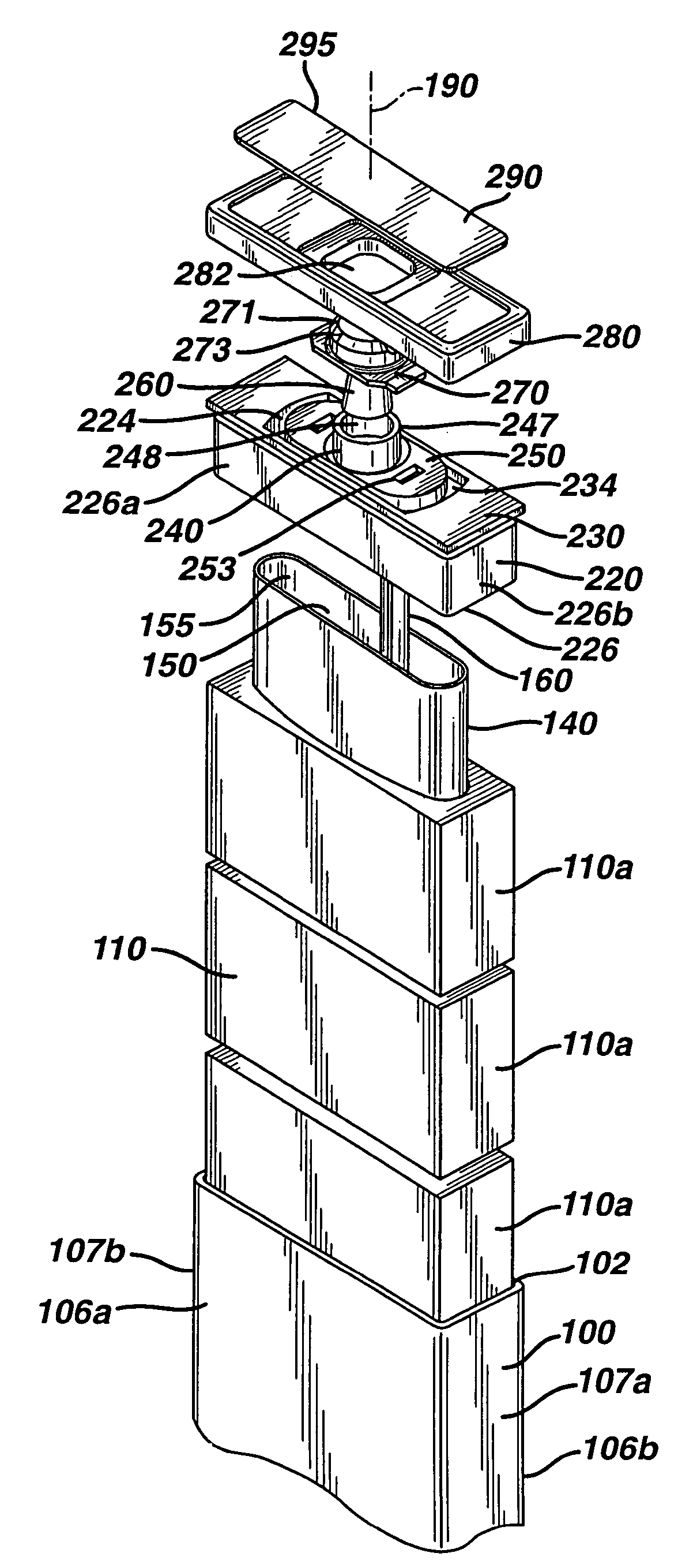
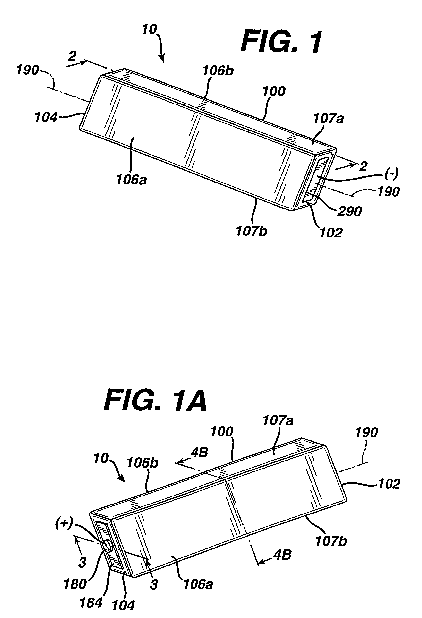
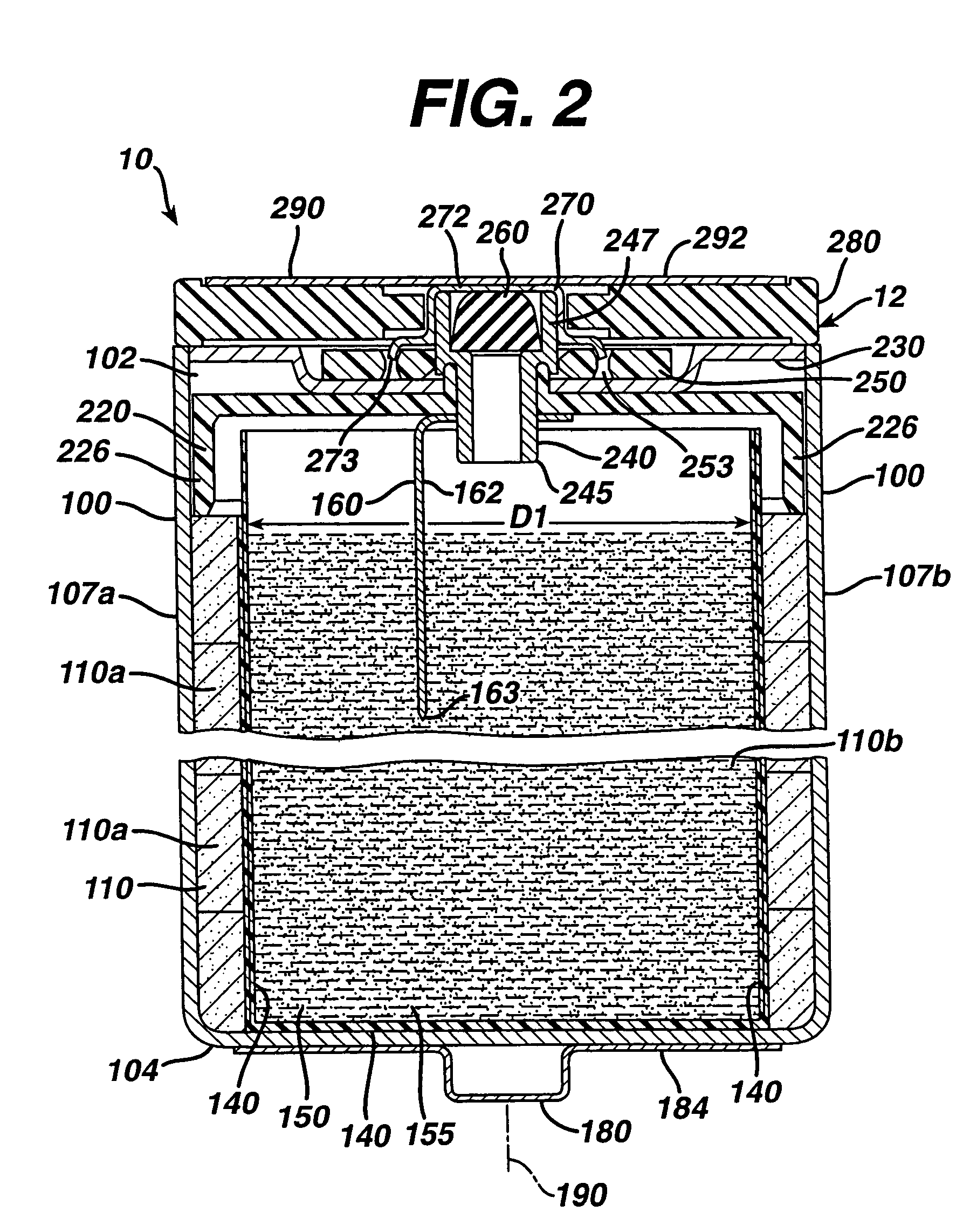
An alkaline cell having a flat housing, preferably of cuboid shape. The cell can have an anode comprising zinc and a cathode comprising MnO2. The housing can have a relatively small overall thickness, typically between about 5 and 10 mm. Cell contents can be supplied through an open end in the housing and an end cap assembly inserted therein to seal the cell. There can be a gap between separator and cathode for insertion of additional electrolyte. The end cap assembly includes a vent mechanism, preferably a grooved vent, which can activate, when gas pressure within the cell reaches a threshold level typically between about 250 and 800 psig (1724×103 and 5515×103 pascal gage). The cell can have a supplemental vent mechanism such as a laser welded region on the surface of the housing which may activate at higher pressure levels.

Description

CROSS REFERENCE TO RELATED APPLICATIONS[0001]This application is a continuation in part of application Ser. No. 10 / 414,750 filed Apr. 16, 2003 now U.S. Pat. No. 7,094,494, which is a continuation in part of application Ser. No. 10 / 336,261 filed Jan. 3, 2003, now U.S. Pat. No. 6,833,215.FIELD OF THE INVENTION[0002]The invention relates to an alkaline battery having a substantially flat outer housing. The invention relates to alkaline battery having an anode comprising zinc, a cathode comprising manganese dioxide, and an electrolyte comprising aqueous potassium hydroxide.BACKGROUND[0003]Conventional alkaline electrochemical cells have an anode comprising zinc and a cathode comprising manganese dioxide. The cell is typically formed of a cylindrical outer housing. The fresh cell has an open circuit voltage (EMF) of about 1.5 volt and typical average running voltage of between about 1.0 to 1.2 Volt in medium drain service (100 to 300 milliamp). The cylindrical housing is initially formed...

Claims


Application Information

Patent Timeline
IPC IPC(8): H01M6/50H01M2/12H01M4/50B65D51/16H01M6/04H01M6/08H01M10/24H01M10/28H01M50/186H01M50/193
CPCH01M2/0426H01M2/08H01M6/08H01M10/28H01M2/1241H01M2/0217Y10T29/4911Y02E60/124Y02E60/10H01M50/103H01M50/169H01M50/3425Y02P70/50H01M50/186H01M50/193
Inventor ANGLIN, DAVIDASHBOLT, MARKBOBOWICK, DEREKFERRIN, ROBERT S.MALGIOGLIO, ANTHONYMERRILL, BRIENSHELEKHIN, ALEXANDERSPECHT, STEVEN J.SYLVESTRE, MATTHEWTRAINER, PHILIPYOPPOLO, ROBERT A.
Owner DURACELL U S OPERATIONS
Why Eureka
Try Eureka