

LED illumination system having an intensity monitoring system
a technology of intensity monitoring and led illumination, applied in the field of light sources, can solve the problems of array complicating the feedback system, individual led output vary, and the feedback system cannot adjust just that led
- Summary
- Abstract
- Description
- Claims
- Application Information
AI Technical Summary
Benefits of technology
Problems solved by technology
Method used
Image

Examples
Embodiment Construction
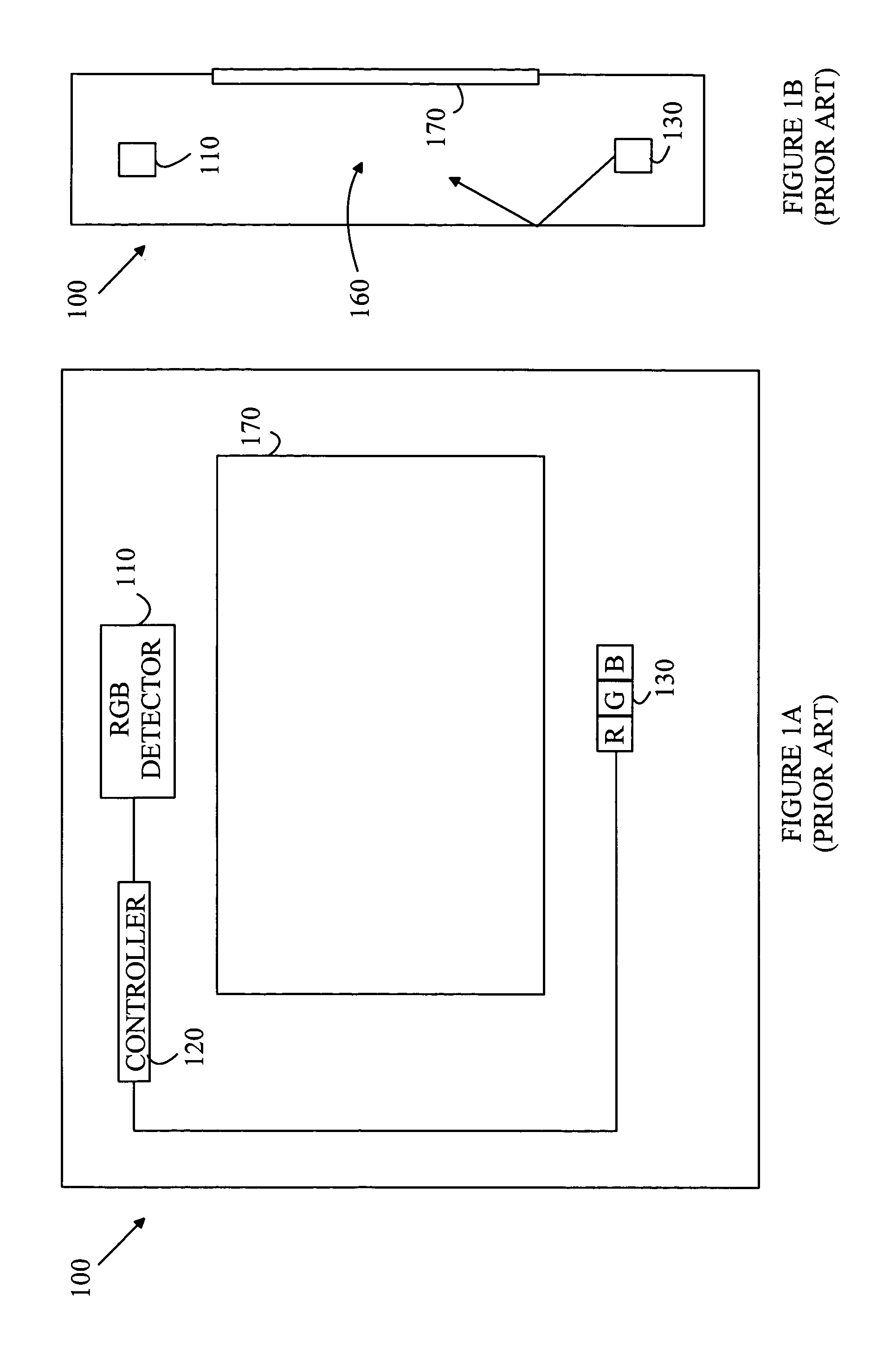
[0015]The manner in which the present invention provides its advantages can be more easily understood with reference to FIGS. 1A and 1B. FIG. 1A is a top view of a prior art display system 100. FIG. 1B is an end view of display system 100. Display system 100 utilizes an LED source 130 having red, blue, and green LEDs to illuminate a display device 170 from a location behind display device 170. For example, display device 170 may include an imaging array constructed from an array of transmissive pixels. Light from LED source 130 is “mixed” in a cavity 160 behind display device 170 to provide uniform illumination of display device 170. The walls of this cavity are typically reflective. A photo-detector 110 measures the intensity of light in cavity 160 at three wavelengths corresponding to the LEDs in LED source 130. A controller 120 uses these measurements in a servo loop to adjust the drive currents of each of the LEDs in LED source 130 to maintain the desired illumination spectrum.
[...
PUM
| Property | Measurement | Unit |
|---|---|---|
| wavelengths | aaaaa | aaaaa |
| wavelength | aaaaa | aaaaa |
| light intensity | aaaaa | aaaaa |
Abstract
Description
Claims
Application Information