Surgical fastener applying apparatus with controlled beam deflection

a technology of beam deflection and surgical fastener, which is applied in the direction of surgical staples, surgical staples, paper/cardboard containers, etc., can solve the problems of increasing the size and/or cost of the surgical stapling apparatus, the distal end of the anvil and/or the receiving half-section of the staple cartridge to deflect, etc., so as to reduce the deflection rate and reduce the distal end deflection rate , the effect of reducing th

Active Publication Date: 2007-11-20
TYCO HEALTHCARE GRP LP
View PDF198 Cites 1484 Cited by
  • Summary
  • Abstract
  • Description
  • Claims
  • Application Information

AI Technical Summary

Benefits of technology

[0024]In this embodiment the deflection control system is a three-stage system. In a three-stage system the deflection control system begins reducing the rate of deflection of the distal end of the channel section in a second stage of deflection, and in a third stage of deflection the deflection control system reduces the rate of deflection of the distal end of the channel member by an additional amount. In operation, the second stage of deflection engages when the first reveal between the side walls of the channel member and the side walls of the first channel section is about zero, whereby the distal end of the channel member and the distal end of the first channel section deflect concomitantly. The third stage of deflection engages when the second reveal between the side walls of the first channel section and the side walls of the second channel section is about zero, whereby the distal end of the channel member, the distal end of the first channel section and the distal end of the second channel section deflect concomitantly.
[0028]In operation, as the distal end of the channel member and the deflection control system deflect in a direction transverse to the longitudinal axis, the distal end of at least one of the plurality of reinforcing plates translates in a longitudinal direction. The deflection control system is a multi-stage system which begins to incrementally reduce the rate of deflection of the distal end of the channel member as a distal end of each elongate slot of each respective reinforcing plate engages the pin member. The deflection control system incrementally reduces the rate at which the distal end of the channel member deflects.
[0030]In operation, as the distal end of the channel member and the deflection system deflect in a direction transverse to the longitudinal axis the distal end of each of the plurality of reinforcing plates translates in a longitudinal direction. The deflection control system is a multi-stage system, wherein the deflection control system begins to incrementally reduce the rate of deflection of the distal end of the channel member as a distal end of each elongate recess of each respective reinforcing plate engages a respective shoulder, the deflection control system incrementally reduces the rate at which the distal end of the channel member deflects.
[0031]According to another aspect of the present disclosure, a deflection control system is provided for a surgical fastener applying apparatus that includes an anvil half-section having a channel member and a cartridge receiving half-section operatively couplable to the anvil half-section. The deflection control system includes an elongate reinforcing assembly having a proximal end operatively engaged with a proximal end of the channel member and a distal end operatively associated with a distal end of the channel member, wherein the reinforcing assembly incrementally reduces deflection of the distal end of the channel member when forces are applied to the distal end of the channel member in a direction transverse to a longitudinal axis of the channel member and normal to a tissue contacting surface of the anvil half-section.
[0034]This deflection control system is a two-stage system. Accordingly, in operation, the deflection control system begins reducing the degree and the rate of deflection of the distal end of the channel member in a second stage of deflection. The second stage of deflection takes effect when the reveal between an upper portion of the hole formed in each reinforcing rib and an upper portion of the cam is zero.

Problems solved by technology

However, it has been noticed that clamping of such tissue between the tissue contacting surfaces of the distal ends of the anvil and staple cartridge receiving half-sections tends to cause the distal ends of the anvil and / or staple cartridge receiving half-sections to deflect.
These approaches increase the size and / or cost of the surgical stapling apparatus.

Method used


Image

  • Surgical fastener applying apparatus with controlled beam deflection
  • Surgical fastener applying apparatus with controlled beam deflection
  • Surgical fastener applying apparatus with controlled beam deflection

Examples


Embodiment Construction

[0060]Preferred embodiments of the presently disclosed surgical fastener applying apparatus will now be described in detail with reference to the drawing figures wherein like reference numerals identify similar or identical elements. In the drawings and in the description which follows, the term “proximal” will refer to the end of the surgical fastener applying apparatus which is closest to the operator, while the term “distal” will refer to the end of the surgical fastener applying apparatus which is furthest from the operator.

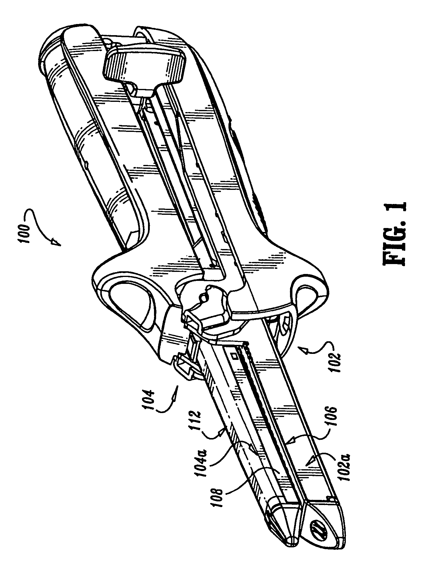
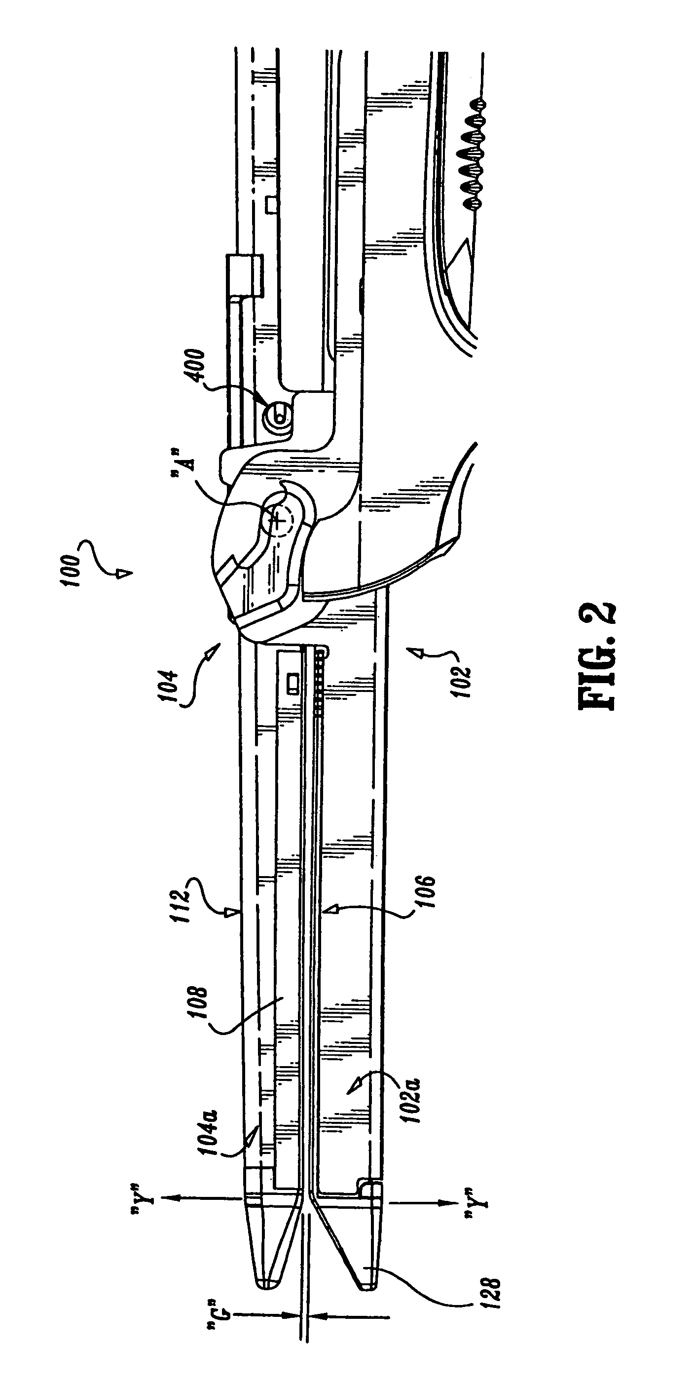
[0061]Referring to FIGS. 1-5, a surgical fastener applying apparatus, in accordance with the present disclosure, is shown generally as 100. Apparatus 100 is particularly adapted to apply surgical staples and includes a cartridge receiving half-section 102, an anvil half-section 104 operatively coupled to cartridge receiving half-section 102, a staple cartridge assembly 106 fixedly or removably supported in a distal end 102a of cartridge receiving half-section...


PUM

PropertyMeasurementUnit
heightaaaaaaaaaa
heightaaaaaaaaaa
heightaaaaaaaaaa

Abstract

A surgical fastener applying apparatus including an anvil half-section having a distal end and a longitudinal axis; a cartridge receiving half-section having a distal end and operatively couplable with the anvil half-section such that the distal ends of the half-sections are in juxtaposed relation; and a deflection control system operatively engaged with and reinforcing the distal end of the anvil half-section when a force is applied to the distal end of the anvil half-section in a direction transverse to the longitudinal axis.

Description

BACKGROUND[0001]1. Technical Field[0002]The present disclosure relates to surgical fastener applying apparatus and, more particularly, to surgical fastener applying apparatus that include a deflection control system for controlling and / or reducing the rate of deflection of an anvil beam.[0003]2. Background of Related Art[0004]Surgical fastener applying apparatus, for example, surgical stapling apparatus, have been developed in which a staple cartridge receiving half-section including a staple cartridge assembly provided at a distal end thereof, is operatively connected (e.g., pivotably connected) to an anvil half-section including an anvil provided at a distal end thereof. The staple cartridge assembly preferably includes a plurality of surgical staples which are ejectable therefrom. The staple cartridge assembly may be manufactured as an integral part of the staple cartridge receiving half-section, or the staple cartridge assembly may be designed and manufactured as a disposable lo...

Claims


Application Information

Patent Timeline
Patent Type & Authority Patents(United States)
IPC IPC(8): A61B17/00A61B17/072A61B18/14
CPCA61B17/07207A61B17/068A61B2017/2926A61B2017/07214A61B17/105
Inventor IVANKO, DAVID
Owner TYCO HEALTHCARE GRP LP
Why Eureka
Try Eureka