

Automotive driveline components manufactured of silicone materials
a technology of silicone materials and drivelines, which is applied in the direction of couplings, mechanical equipment, rotary machine parts, etc., can solve the problems of shortening the effective life of the boot, reducing the sealing effectiveness of the boot, and still undesirable wear, so as to achieve constant operating temperatures and increase stiffness
- Summary
- Abstract
- Description
- Claims
- Application Information
AI Technical Summary
Benefits of technology
Problems solved by technology
Method used
Image

Examples
Embodiment Construction
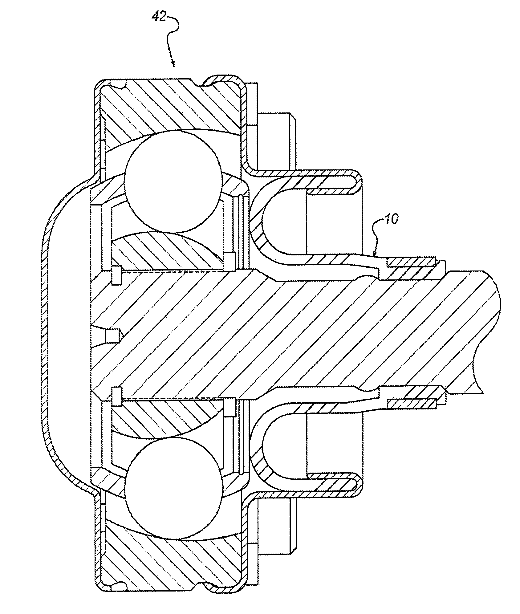
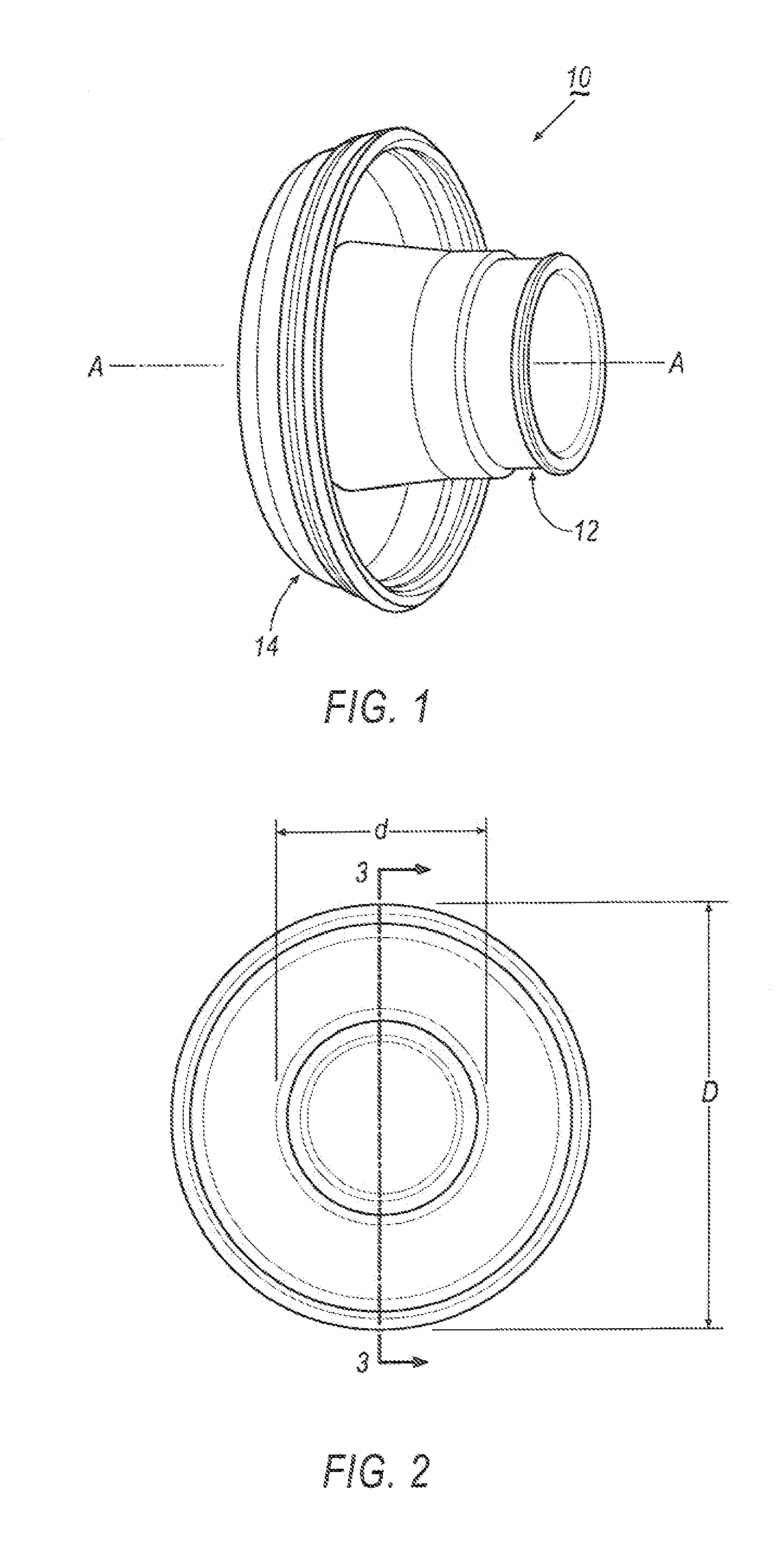
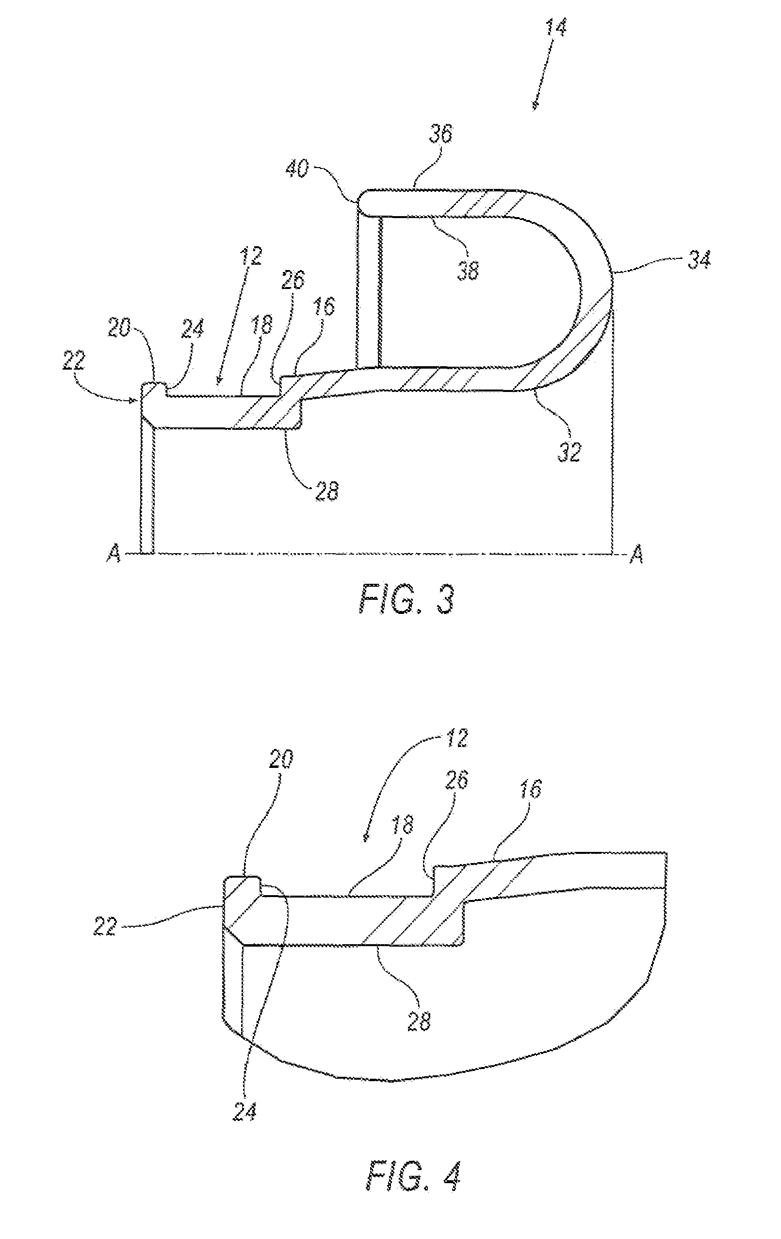
[0014]Referring to FIGS. 1-5, an embodiment of a flexible boot assembly, indicated generally at 10, for use with a constant velocity joint 42 (see FIG. 5) in accordance with the present invention, is shown. Boot assembly 10 includes a first sealing end portion 12, and a second sealing end portion 14. First sealing end portion 12 has a first outer diameter d that is less than the outer diameter D of second sealing end portion 14. Both first and second sealing end portions 12, 14 are positioned around a common axis A-A.
[0015]An outside surface 16 of first end portion 12 includes an annular groove 18 formed therearound. An annular ridge 20 extends around the distal end 22 of first sealing end portion 12, adjacent to annular groove 18. Annular ridge 20 defines a first flange surface 24. In one embodiment, first flange surface 24 is generally planar so as to be generally perpendicular to annular groove 18. In another embodiment, first flange surface 24 may slope inwardly so as to be angl...
PUM
| Property | Measurement | Unit |
|---|---|---|
| operating temperature | aaaaa | aaaaa |
| diameter | aaaaa | aaaaa |
| length | aaaaa | aaaaa |
Abstract
Description
Claims
Application Information