Shoulder prosthesis

a shoulder and hip technology, applied in the field of bone prosthesis, can solve the problems of inability to adjust, and difficulty in obtaining a large number of devices, and the success of shoulder implants is less common than the common problem of hip replacement, so as to achieve the effect of reducing the number of devices and reducing the cost of stocking the large number of devices

Inactive Publication Date: 2007-11-20
ACUMED
View PDF373 Cites 81 Cited by
  • Summary
  • Abstract
  • Description
  • Claims
  • Application Information

AI Technical Summary

Benefits of technology

[0010]The present invention is a system and method for installing a shoulder prosthesis having a head and an elongate stem portion including a proximal end connected to the head, a distal section for insertion into a m

Problems solved by technology

As a result of anatomical constraints and challenges in the shoulder, shoulder implants have historically been much less successful and less common than hip replacements.
While simple to construct, unitary implants do not offer any adjustability to accommodate the natural variations in size and geometry that occur among joints of different patients.
Stocking the large number of devices is a significant expense with one-piece designs, and in some cases a surgeon may not be provided with sufficient flexibility to achieve an ideal fit to the patient.
Unfortunately, rotating an offset head can introduce a medial/lateral and/or superior/inferior offset at the same time the anterior/posterior positioning is adjusted.
Furthermore, the offset between the center of the taper lock and the geometrical center of the head creates a torque which tends to rotate the head relative to the remainder of the implant, thereby increasing the chance of loosening of the head.
As

Method used


Image

  • Shoulder prosthesis
  • Shoulder prosthesis
  • Shoulder prosthesis

Examples


Embodiment Construction

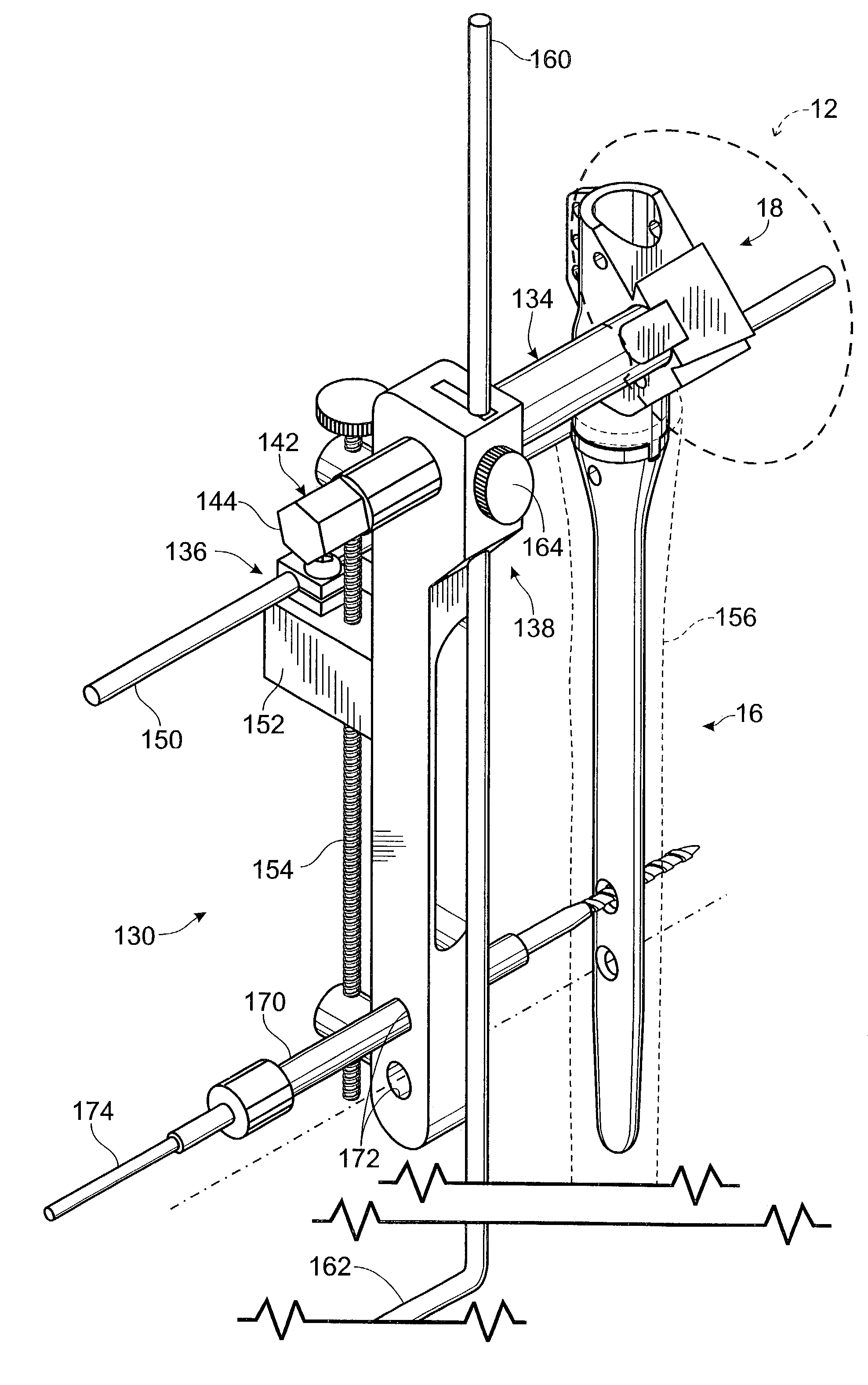
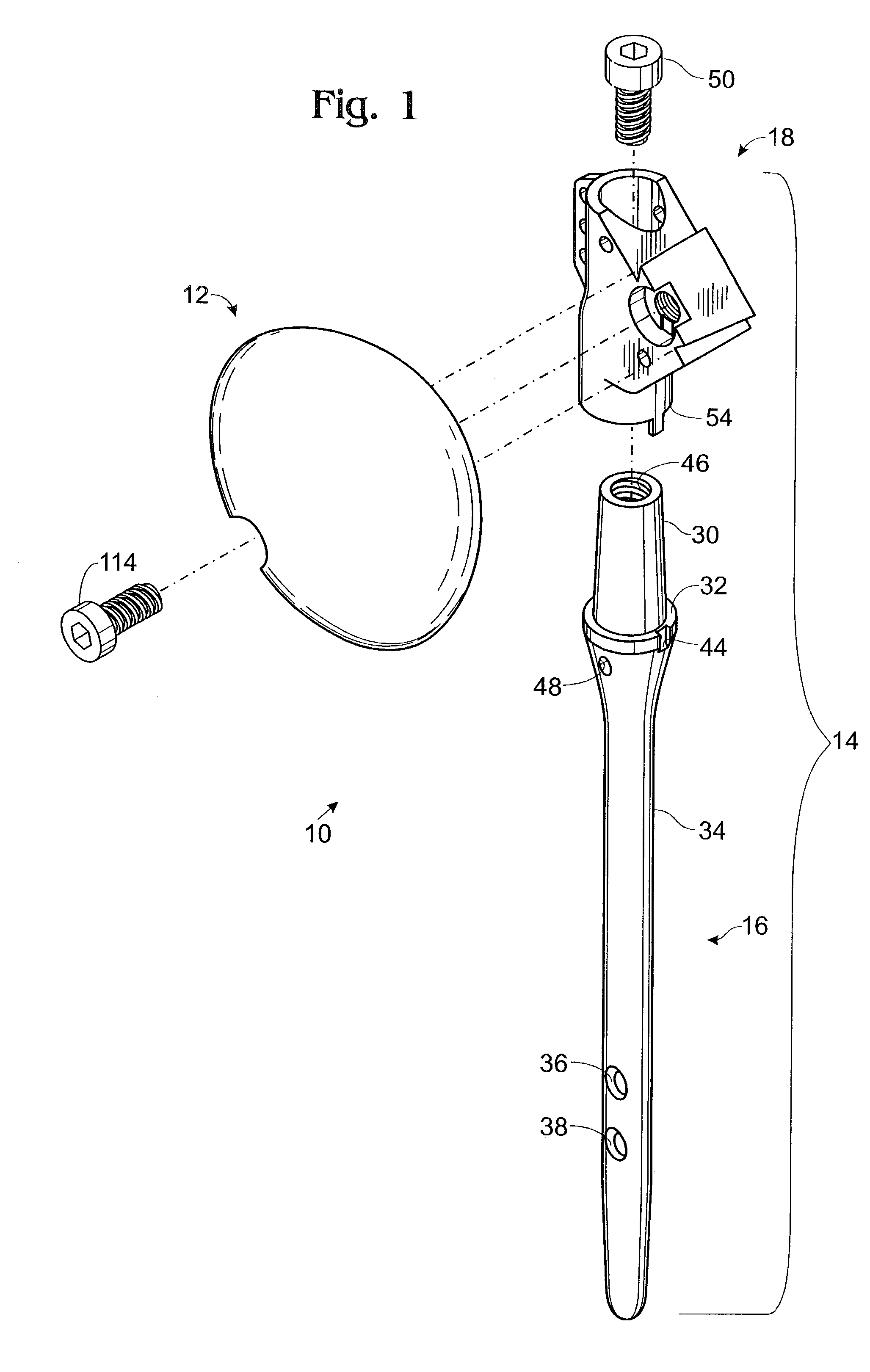
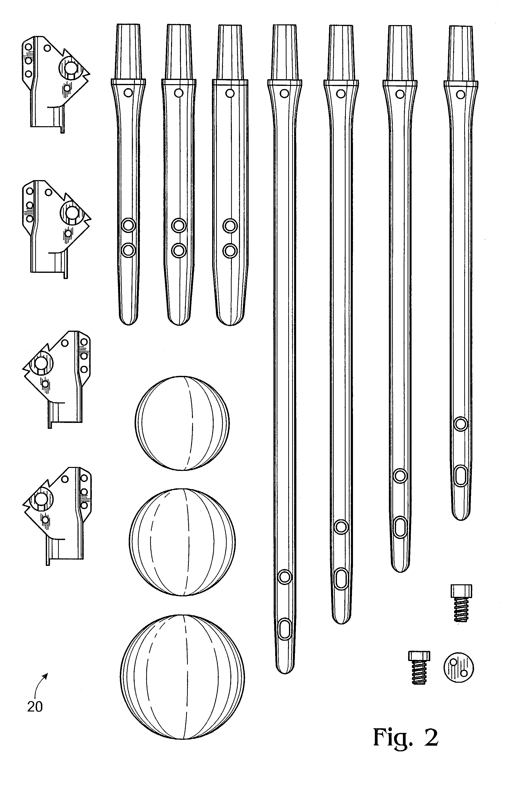
[0035]A shoulder implant constructed according to the present invention is shown generally at 10 in FIG. 1. Implant 10 includes a head 12 and a stem 14. The stem preferably includes a distal shaft 16 and a body 18. The components making up implant 10 are preferably chosen from a kit 20 of interchangeable shafts, bodies and heads, as shown in FIG. 2. By selecting an appropriate shaft, body and head from kit 20, a surgeon is able to create an implant that is sized properly for almost any patient. Positional references such as anterior / posterior, medial / lateral and proximal / distal used herein are made with reference to an implant as it would be positioned in a patient.

[0036]Shaft 16 is shown in greater detail in FIG. 3 and includes a proximal tapered end 30 extending distally to a shoulder 32 which tapers smoothly into a cylindrical medial region 34 with distal locking holes 36, 38. As can be seen in FIG. 2, the shaft can have a medial region of varying diameter and / or varying length. ...


PUM


Abstract

A system and method for installing a shoulder prosthesis. The method includes removing the original humeral head and shaping the proximal end of the humerus with one or more implements to prepare the humerus to receive the shoulder prosthesis.

Description

CROSS-REFERENCE TO RELATED APPLICATIONS[0001]This application is a continuation of U.S. patent application Ser. No. 09 / 507,564, filed Feb. 18, 2000 now U.S. Pat. No. 6,494,913, which is a continuation-in-part of U.S. patent application Ser. No. 09 / 191,928, filed Nov. 13, 1998, now U.S. Pat. No. 6,102,953, which is a continuation-in-part of U.S. patent application Ser. No. 09 / 165,475, filed Oct. 2, 1998, now U.S. Pat. No. 6,193,758, and U.S. patent application Ser. No. 09 / 040,504, filed Mar. 17, 1998, now U.S. Pat. No. 5,961,555. These priority applications are each incorporated herein by reference in their entirety for all purposes.FIELD OF THE INVENTION[0002]This invention relates generally to bone prostheses and more particularly to a system for facilitating installation of a shoulder prosthesis.BACKGROUND OF THE INVENTION[0003]When a joint, such as the hip or shoulder, becomes impaired due to arthritis, disease or trauma, it is sometimes necessary to replace all or part of the jo...

Claims


Application Information

Patent Timeline
IPC IPC(8): A61F2/40A61B17/58A61B17/04A61B17/06A61B17/17A61B17/84A61F2/00A61F2/02A61F2/30A61F2/46
CPCA61F2/40A61F2/4657A61B17/06166A61F2002/4687A61B17/842A61B17/848A61B2017/0404A61F2/4059A61F2/4637A61F2/4684A61F2002/30224A61F2002/30235A61F2002/30332A61F2002/30382A61F2002/30385A61F2002/30387A61F2002/30507A61F2002/30538A61F2002/3054A61F2002/30553A61F2002/30574A61F2002/30604A61F2002/30616A61F2002/30617A61F2002/30685A61F2002/30708A61F2002/30714A61F2002/30772A61F2002/30774A61F2002/30777A61F2002/30785A61F2002/30789A61F2002/3079A61F2002/30792A61F2002/30794A61F2002/30884A61F2002/30902A61F2002/30925A61F2002/3097A61F2002/4018A61F2002/4051A61F2002/4062A61F2002/4074A61F2002/4077A61F2002/4631A61F2002/4641A61F2002/4677A61F2220/0025A61F2220/0033A61F2230/0069A61F2250/0006A61F2250/0008A61F2250/0084A61F2250/0089A61F2250/0097A61B2017/1778A61B17/1753A61F2002/30331A61F2002/3071A61B17/1778
Inventor HUEBNER, RANDALL J.
Owner ACUMED
Why Eureka
Try Eureka