Traveling sprinkler incorporating automatic water supply valve docking station

a technology of automatic water supply valve and travel irrigation, which is applied in watering devices, horticulture, agriculture, etc., can solve the problems of canal water being often dirty, few if any successful machines, and the latter machines, however, have drawbacks

Active Publication Date: 2007-11-27
PROJECT 088
View PDF57 Cites 53 Cited by
  • Summary
  • Abstract
  • Description
  • Claims
  • Application Information

AI Technical Summary

Benefits of technology

[0006]The present invention provides, in its simplest form, a unique docking module or docking station for use with a single large-volume sprinkler on a wheeled cart that moves along an above-ground water supply pipe, and that successively docks with and actuates individual water supply valves in hydrants located along the pipe. Power to the cart drive wheels may be provided by a pair of conventional 12-volt batteries carried on the cart. A programmable logic controller (PLC), also carried on the cart, controls the movement of the cart, the speed of the cart, and both the docking and sprinkler operations.
[0017]In order to further facilitate the docking operation, a new hydrant design has been adopted for use with the docking station of this second embodiment. The hydrant may include a standard vertical pipe or riser fixed to the water supply pipe. At the upper end of the riser, a new valve housing is attached by any suitable means and incorporates a spring-loaded valve assembly. The upper end of the valve housing is formed with an exterior, round, horizontal flange or plate that cooperates with the docking station during capture of the hydrant. By making the flange round, the hydrant is easily approached and engaged from any direction. The valve itself projects above the top of the flange to facilitate alignment with the hydrant valve actuator on the docking station. Another alternative is the use of a conversion kit to render existing hydrants (with compatible valves) useable with the docking station.
[0020]The cart as described engages and follows an above-ground supply pipe. The cart can also be used with underground pipe, with only the hydrants visible, and with guidance provided by wire, GPS, etc. In such cases, the front guide wheels are modified to run on the ground rather than on the supply pipe itself. In addition, for carts capable of travel in opposite directions, two pairs of vertically-oriented, angled guide wings respectively mounted on the front and back of the docking station supporting frame, along with one pair of horizontally-oriented front and back guide wings, assist in “capturing” the hydrants projecting upwardly from the underground supply pipe. In this regard, the docking station itself is also operable in opposite forward and rearward directions of movement of the cart, with no change or adjustment in any of the component parts. For single direction carts, only front guide wings are required. In this regard, and for purposes of this application, any use of “front” or “forward,” etc. is intended to refer to the ends of the cart, docking station, etc. that lead in the direction of initial movement of the cart, i.e., along a path P1 as shown in FIG. 1. Use of “back” or “rearward,” etc. is intended to refer to the opposite ends of the cart, docking station, etc. that trail in the movement along path P1.

Problems solved by technology

The various machines described in the above patents have significant drawbacks and disadvantages, to the extent that there are few if any successful machines of this type on the market today.
The latter machines, however, also have drawbacks.
For example, canal water is often dirty and can foul and clog the valves, sprinklers and other components.
In still other cases, complex mechanisms have been proposed for automatic docking with hydrants spaced along the length of a water supply pipe.
One of the problems with these arrangements is that the hydrant risers must be held firmly in concrete, or welded onto steel pipe.
In addition, alignment or docking mechanisms have been complex and costly to maintain.
As a result, reliable docking under various conditions has proven to be an elusive goal.

Method used


Image

  • Traveling sprinkler incorporating automatic water supply valve docking station
  • Traveling sprinkler incorporating automatic water supply valve docking station
  • Traveling sprinkler incorporating automatic water supply valve docking station

Examples


Embodiment Construction

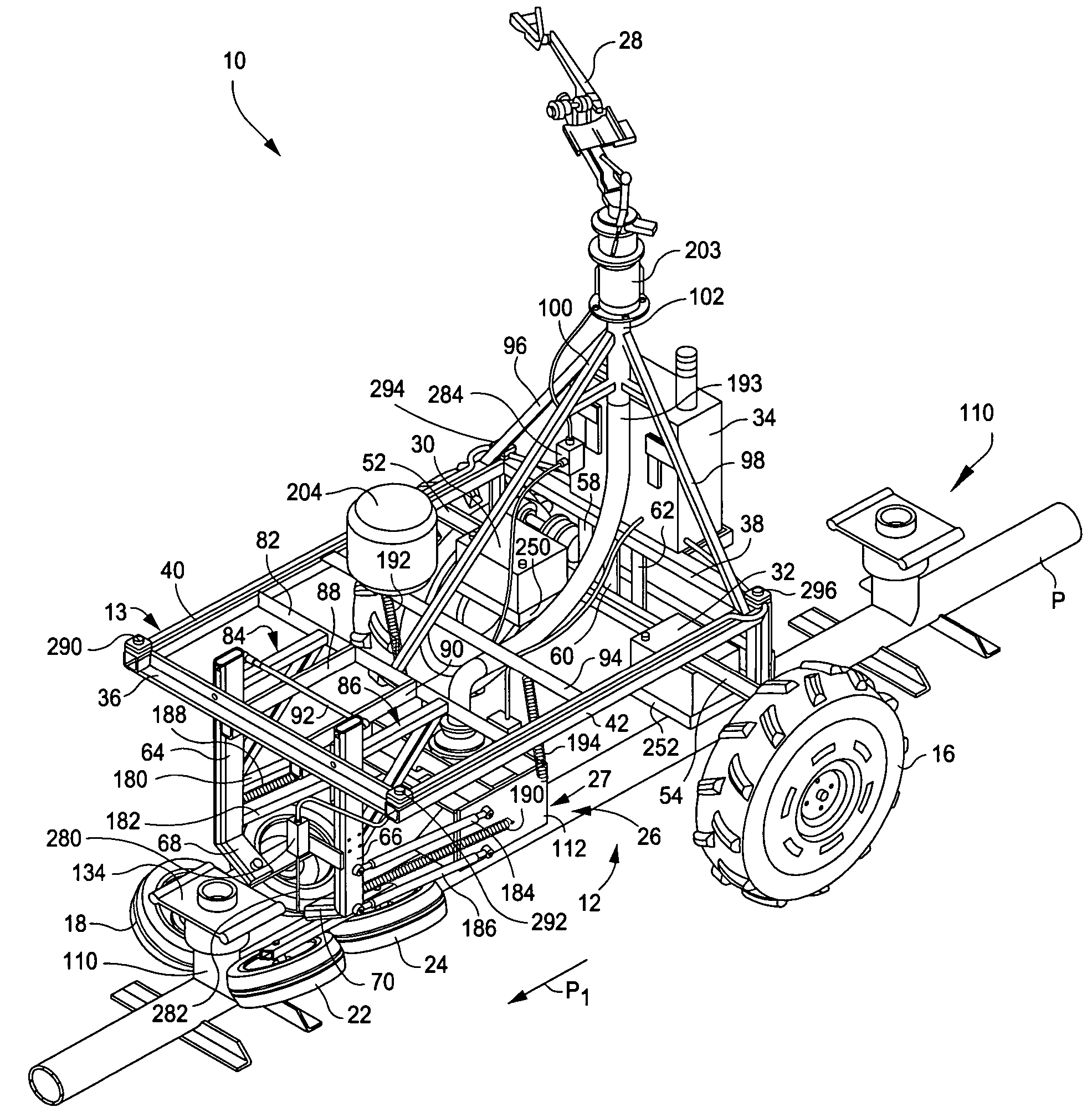
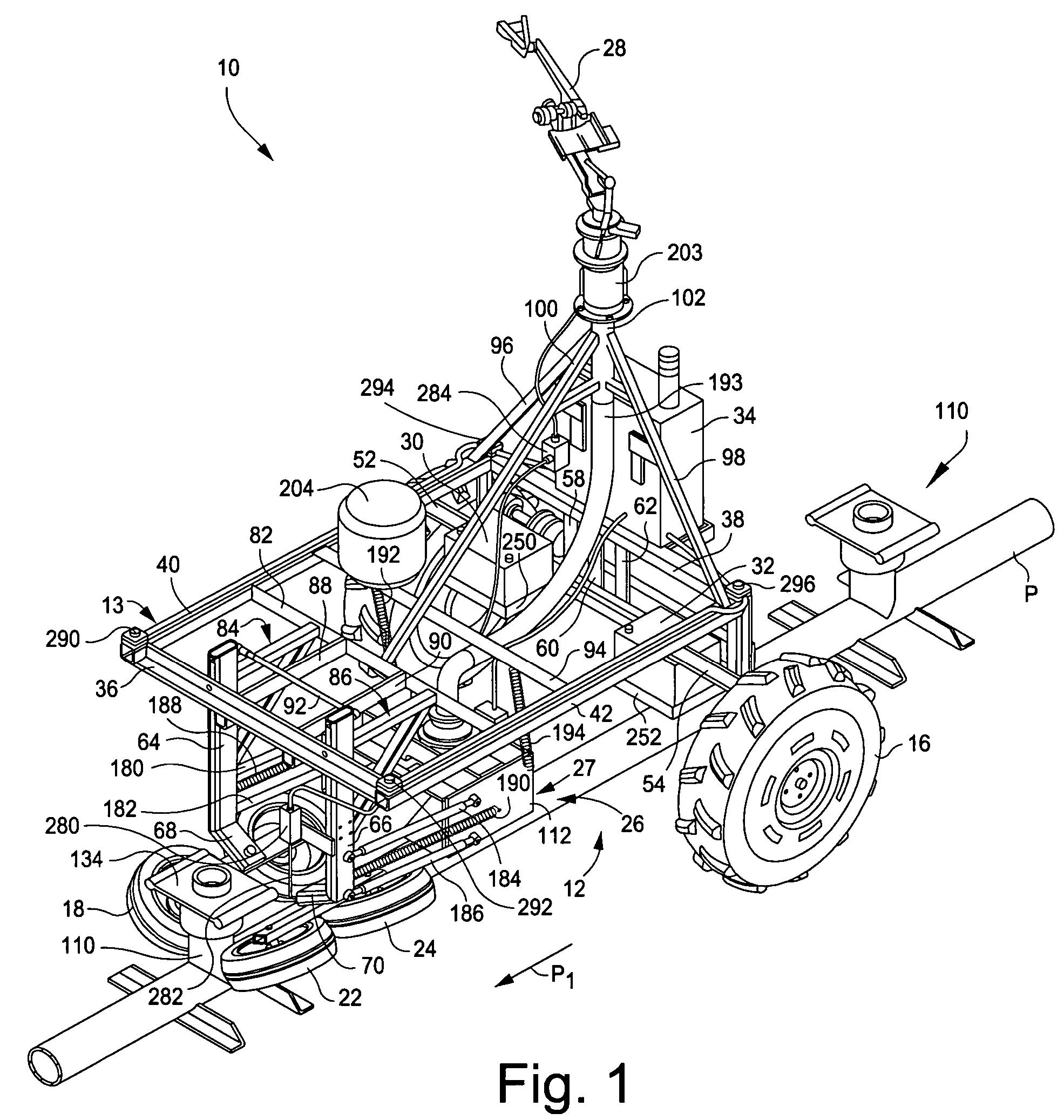
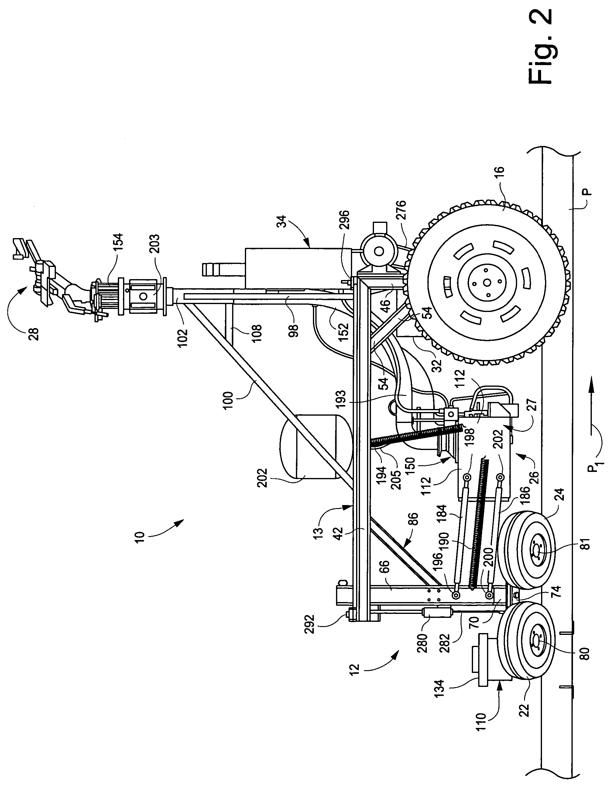
[0063]With reference initially to FIGS. 1-5, the traveling sprinkler 10 generally includes a cart 12; a pair of rear drive wheels 14, 16; two pairs of forward guide wheels 18, 20 and 22, 24; a docking station 26 communicating with a single large-volume sprinkler 28; a pair of 12-volt batteries 30 and 32; and a programmable logic controller (PLC) 34.

[0064]More specifically, the cart 12 is formed by a rectangular steel or other suitable metal (e.g., aluminum) frame 13 that includes parallel front and rear rails 36, 38 connected by parallel side rails 40, 42 welded together to form a rigid main frame subassembly (or simply, main frame). Vertical frame members 44, 46 extending downwardly at the rear of the main frame support the drive wheels 14, 16 via conventional stub axles 48, 50. The main frame is reinforced at the rear by angled rails 52, 54 extending between the vertical frame members 44, 46 and the side rails 40, 42. A crossbeam 56 extends between the vertical frame members 44, 4...


PUM


Abstract

A docking station module for fluidly connecting a mobile irrigation apparatus to a stationary hydrant water supply valve mounted on a water supply pipe, the module comprising a hydrant valve actuator resiliently suspended from a frame for floating movement in at least three mutually substantially perpendicular directions relative to the hydrant water supply valve.

Description

[0001]This application claims priority from provisional application Ser. No. 60 / 496,902, filed Aug. 22, 2003.TECHNICAL FIELD[0002]This invention relates to a traveling irrigation sprinkler, and particularly to a cart that is adapted to follow a water supply pipe, and that incorporates a docking station or module adapted to successively engage and actuate water supply valves located along the pipe.BACKGROUND OF THE INVENTION[0003]Traveling sprinklers that are adapted to follow an above-ground water supply pipe, and to engage in succession a number of water supply valves located along the pipe, are described in various prior patents, among them U.S. Pat. Nos. 3,575,200; 3,970,102; 3,984,052; and 4,240,461. There are other traveling irrigation machines known as “linear move” or “lateral move” machines that include large wheel-supported booms fitted with multiple sprinkler devices, where the drive tower is adapted to engage and actuate a forward supply valve before a trailing valve is d...

Claims


Application Information

Patent Timeline
Patent Type & Authority Patents(United States)
IPC IPC(8): B05B3/00A01G25/09B05B3/18A01GF28F1/00
CPCA01G25/097
Inventor SINDEN, JOSEPH DANIELNESS, REX DANIELLEINWEBER, CHAD DANIELBERRIER, RICHARD JOHNNELSON, CRAIGNELSON, BARTON R.
Owner PROJECT 088
Why Eureka
Try Eureka