
Electronic park brake valve system for air brakes vehicles

a technology of electronic park and air brakes, applied in the direction of brake cylinders, anti-theft devices, braking systems, etc., can solve the problems of difficult installation of valves and associated air hoses, difficult maintenance, and difficulty in finding and fixing air leakag

Active Publication Date: 2007-11-27
HALDEX BRAKE
View PDF16 Cites 4 Cited by
  • Summary
  • Abstract
  • Description
  • Claims
  • Application Information

AI Technical Summary

Benefits of technology

[0009]Accordingly, it is an object of the present invention to provide a pneumatic brake system for heavy vehicles which does not require a significant amount of plumbing running in a complex web to connect various system components.
[0010]Another object of the present invention is to provide a pneumatic brake system for heavy vehicles having the above characteristics and which does not require plumbing that is expensive, heavy and relatively difficult to install and which can be installed relatively quickly.
[0011]A further object of the present invention is to provide a pneumatic brake system for heavy vehicles having the above characteristics and which does not suffer from long delays in achieving required system pressures such that parking brake release timing is satisfactory.
[0012]Still another object of the present invention is to provide a pneumatic brake system for heavy vehicles having the above characteristics and which does not employ valves and system components which themselves are expensive, take up a large amount of space, and significantly add to the vehicle's weight.

Problems solved by technology

Additionally, it can be difficult to install the valve and associated air hoses because of the tight area in which they go behind the dash.
Furthermore, maintenance can be difficult in a case where there is an air leak in the valve or associated hoses.
The air leak can be difficult to find and repair due to the restricted area of the dash.
However, the brake systems disclosed in all of these references still suffer from a number of disadvantages.
One of such disadvantages relates to the complexity of such systems.
Such systems often require a significant amount of plumbing running in a complex web to connect the various system components.
Not only is this large amount of plumbing expensive, heavy and relatively difficult to install (thereby requiring a relatively large amount of time to install), but the potentially long lengths of plumbing between components can lead to delays in achieving required system pressures, such that, for example, parking brake release timing is increased.
Moreover, the valves and system components themselves can be expensive, take up a large amount of space, and significantly add to the vehicle's weight.
What is desired, therefore, is a pneumatic brake system for heavy vehicles which does not require a significant amount of plumbing running in a complex web to connect various system components, which does not require plumbing that is expensive, heavy and relatively difficult to install and which can be installed relatively quickly, which does not suffer from long delays in achieving required system pressures such that parking brake release timing is satisfactory, and which does not employ valves and system components which themselves are expensive, take up a large amount of space, and significantly add to the vehicle's weight.

Method used


Image

  • Electronic park brake valve system for air brakes vehicles
  • Electronic park brake valve system for air brakes vehicles
  • Electronic park brake valve system for air brakes vehicles

Examples


Embodiment Construction

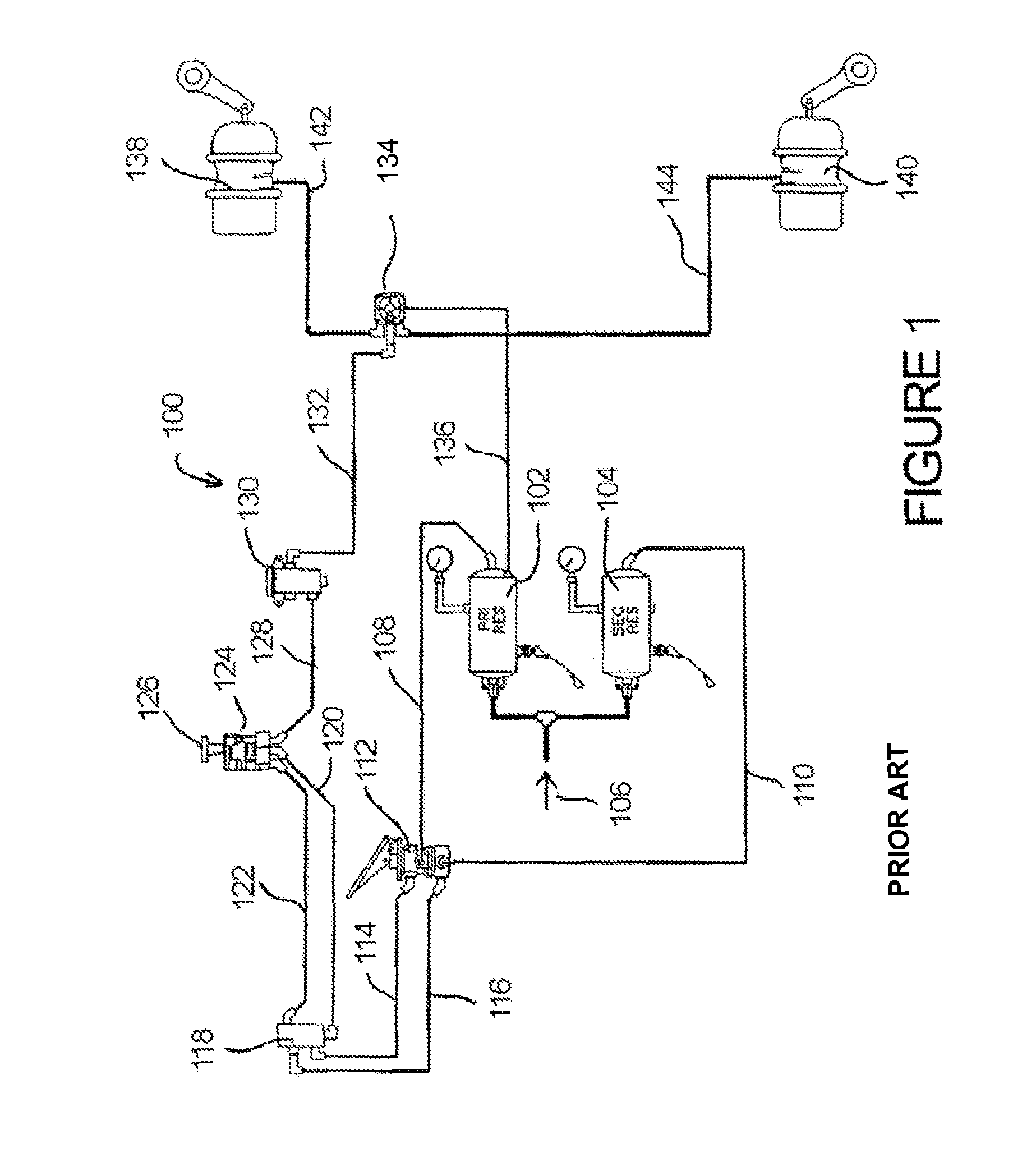
[0024]Referring first to FIG. 1, a typical prior art pneumatic brake system 100 for heavy vehicles is shown. The system 100 includes a primary pressurized air supply reservoir 102 and a secondary pressurized air supply reservoir 104, both of which receive pressurized air from a pressurized air source (indicated by arrow 106), which typically takes the form of a compressor. Primary and secondary pressurized air supply reservoirs 102,104 are connected via conduits 108, 110 to a brake pedal 112 which is disposed within the cab of the vehicle, typically within easy reach of the foot of the vehicle's driver.

[0025]Brake pedal 112 is connected via conduits 114, 116 to a manifold 118, which in turn is connected via conduits 120, 122 to a push / pull double check (PPDC) valve 124, which typically includes a push / pull hand lever 126 within the cab of the vehicle, typically located on the vehicle dash within reach of the driver. PPDC valve 124 is connected, via conduit 128 to an inversion valve ...


PUM


Abstract

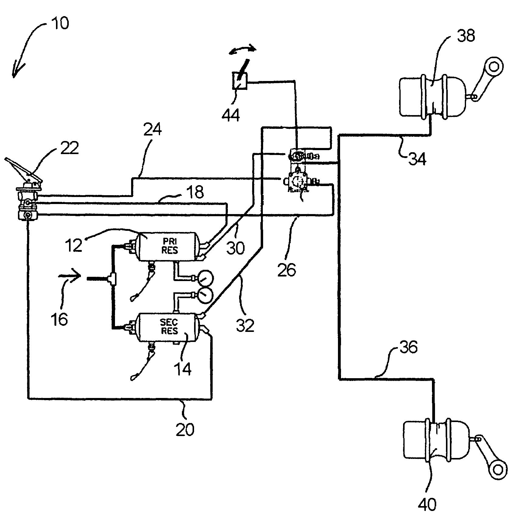
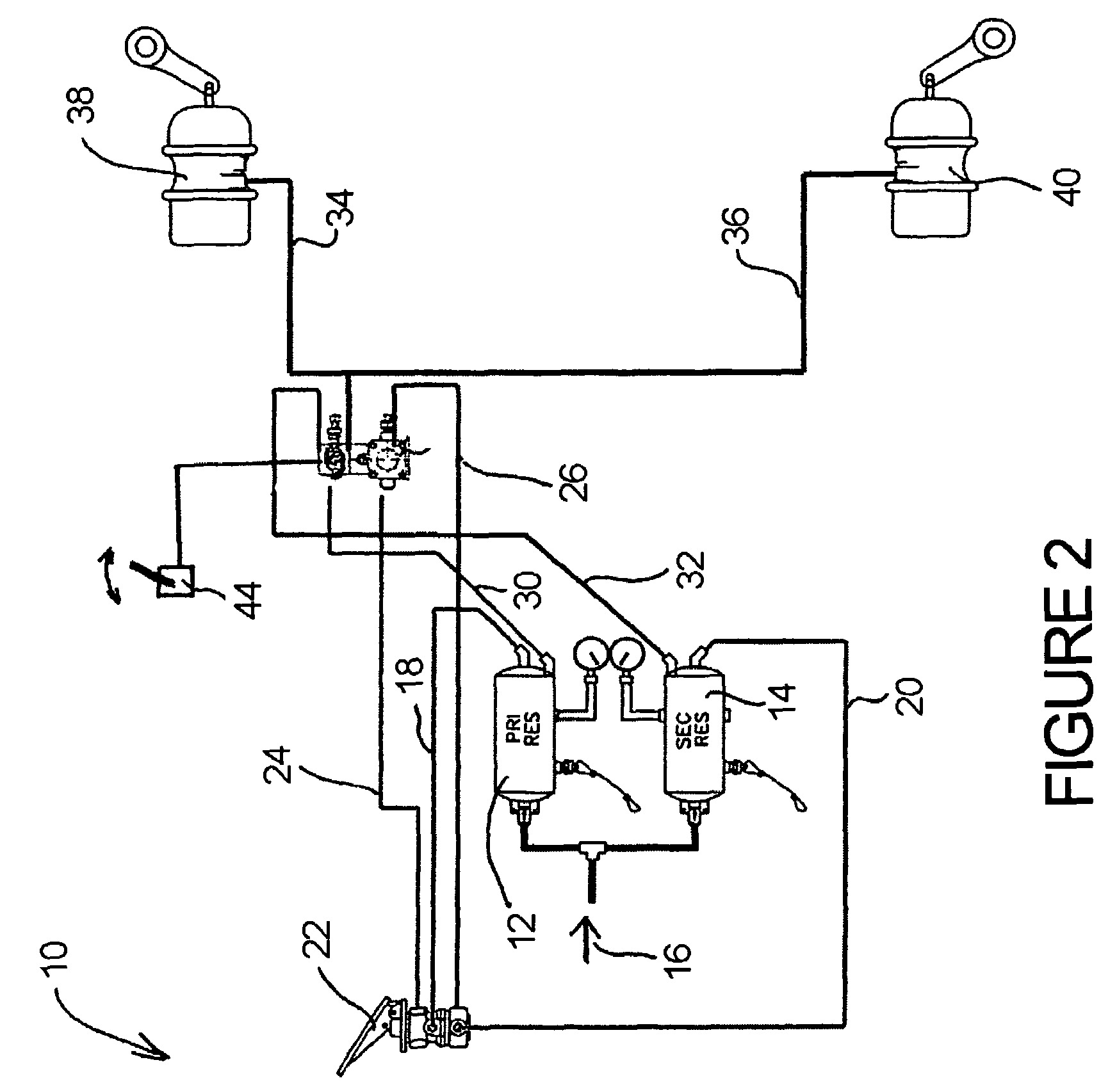
A vehicle brake system includes a source of fluid pressure adapted to supply a braking force a brake actuator including a parking brake chamber, and a combination valve fluidly coupling the brake actuator to the source of pressure, the combination valve having an inlet fluidly coupled to the source of pressure and an outlet fluidly coupled to the brake actuator. The combination valve includes within a single housing (i) a solenoid responsive to electrical signals to move from one position in which the parking brake chamber is fluidly coupled to the source of pressure in order to pressurize the parking brake chamber and release the parking brake, and another position in which the parking brake chamber of the brake actuator is vented in order to exhaust pressure within the parking brake chamber so that the parking brake is applied, and (ii) at least one of a manifold, an inversion valve, a double check valve and an anti-compounding valve.

Description

FIELD OF THE INVENTION[0001]The present invention relates to pneumatic brake systems such as those employed in heavy vehicles, and more specifically to control valves used in such systems, particularly those used in parking brake systems.BACKGROUND OF THE INVENTION[0002]The majority of current heavy vehicle brake systems use compressed air to apply the brakes. In such systems, control signals are typically transmitted from the driver of the vehicle to the control valves of the brake system, and the brakes are applied. These types of brakes are generally divided into two categories: service brakes and parking brakes. Service brakes are used primarily to slow the vehicle to a stop when the vehicle is moving. Parking brakes are used primarily for helping to prevent the vehicle from moving from a parked position, and may also be used in an emergency situation to slow a moving vehicle when the service brakes have failed, in order to provide a redundant brake circuit.[0003]For service bra...

Claims


Application Information

Patent Timeline
Patent Type & Authority Patents(United States)
IPC IPC(8): B60T13/74
CPCB60T13/38B60T17/04B60T15/04B60T13/26B60T13/00
Inventor HOOVER, JOERUDOLPH, ROBERTENGELBERT, DAVID G.HAMILTON, NOBLE
Owner HALDEX BRAKE
Learn More