Fluid-tight coupling system for corrugated pipe

a technology of corrugated pipes and coupling systems, which is applied in the direction of fluid pressure sealed joints, pipe joints, sleeves/socket joints, etc., can solve the problems of leakage between the spigot and the bell, exasperation of the problem of slippage, and the coefficient of friction of the gasket is reduced, so as to reduce the force needed for the spigot to be inserted. , the effect of reducing the coefficient of friction of the gask

Inactive Publication Date: 2007-04-05
PRINSCO
View PDF50 Cites 17 Cited by
  • Summary
  • Abstract
  • Description
  • Claims
  • Application Information

AI Technical Summary

Benefits of technology

[0018] As a further advantage of the present invention, the positioning of the gasket at the end of the pipe allows for easier installation, inasmuch as there will be no friction between the gasket and any other surface while inserting the spigot end into the bell. As stated previously, with gaskets using axial surfaces for sealing, the dimensional control between the bell and the gasket is very critical. Closer tolerances mean better sealing, but also lead to more difficult installation. Normal practice is to use a lubricant on the gasket during installation to lower the gasket's coefficient of friction, thereby reducing the force needed to insert the spigot into the bell. The design of conventional couplers with axial sealing surfaces inherently involves compromise between better sealing and easier installation. Consequently, it is not unusual when designing such conventional couplers to have to reconstruct the joint-forming molds a number of times before finding an acceptable balance between sealing and ease of installation. This problem is effectively eliminated in the present coupling design.
[0019] As still another advantage of the present invention, since placement of the gasket is at the end of the pipe, no external banding is required to keep the bell from expanding under pressure, as internal and external fluid pressures are substantially transferred and absorbed axially through the coupling system. Notwithstanding the above, as an optional feature of the present coupling system, a supplemental or alternative annular channel may be formed in the outer corrugated sidewall of the spigot pipe for sealing in a conventional manner against the inner axial surface formed by the bell, if so desired.

Problems solved by technology

First, if there is insufficient restraint to hold the radially compressed gasket in place, the lateral or axial force exerted on such gasket due to hydrostatic pressure can cause the gasket to slip or “blow out,” thereby causing leakage between the spigot and bell.
However, in order to facilitate joint assembly, it is often necessary to apply a lubricant to the gasket, which lowers its coefficient of friction, thus exasperating the problem of slippage.
This minimizes the force on the gasket when the joint is pressurized, but, from a manufacturing standpoint, can be difficult to hold the tight tolerances required.
Also, while closer tolerances mean better sealing, it does lead to more difficult installation, due to the friction between the gasket and the bell.
Another issue with the current bell and spigot design utilizing a radially compressed gasket is that the internal water pressure in the joint system causes the bell to expand at the point of intersection with the gasket, thereby causing further leakage.
The bell has to be sufficiently stiff to restrain this force, and with larger pipe sizes (e.g. 42″ and larger), it becomes quite difficult to manufacture a bell with enough stiffness to meet this criteria.
Therefore, as stated previously, some manufacturers have resorted to adding reinforcing bands around the exterior of the bell to keep the bell from expanding (and thereby creating a leak in the system).
These bands can be effective, but are also costly and add to the manufacturing process.
It is evident then that the current coupling systems used for corrugated plastic pipe in watertight gravity-flow drainage and sewage applications have inherent limitations which make them more prone to leakage problems when subjected to increasing internal and external hydrostatic pressures, particularly when those pressures exceed 10 psi.

Method used


Image

  • Fluid-tight coupling system for corrugated pipe
  • Fluid-tight coupling system for corrugated pipe
  • Fluid-tight coupling system for corrugated pipe

Examples


Embodiment Construction

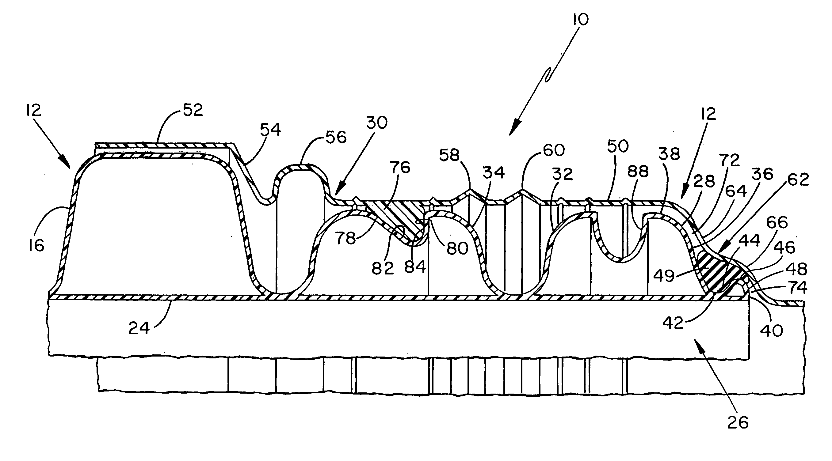
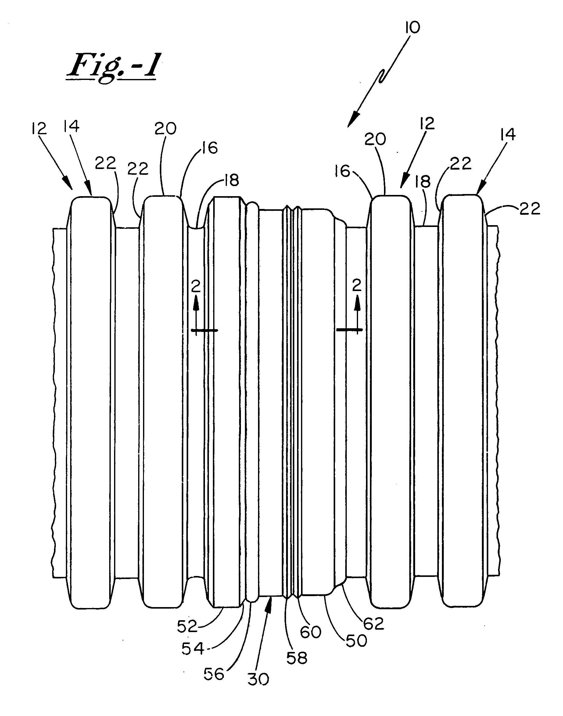
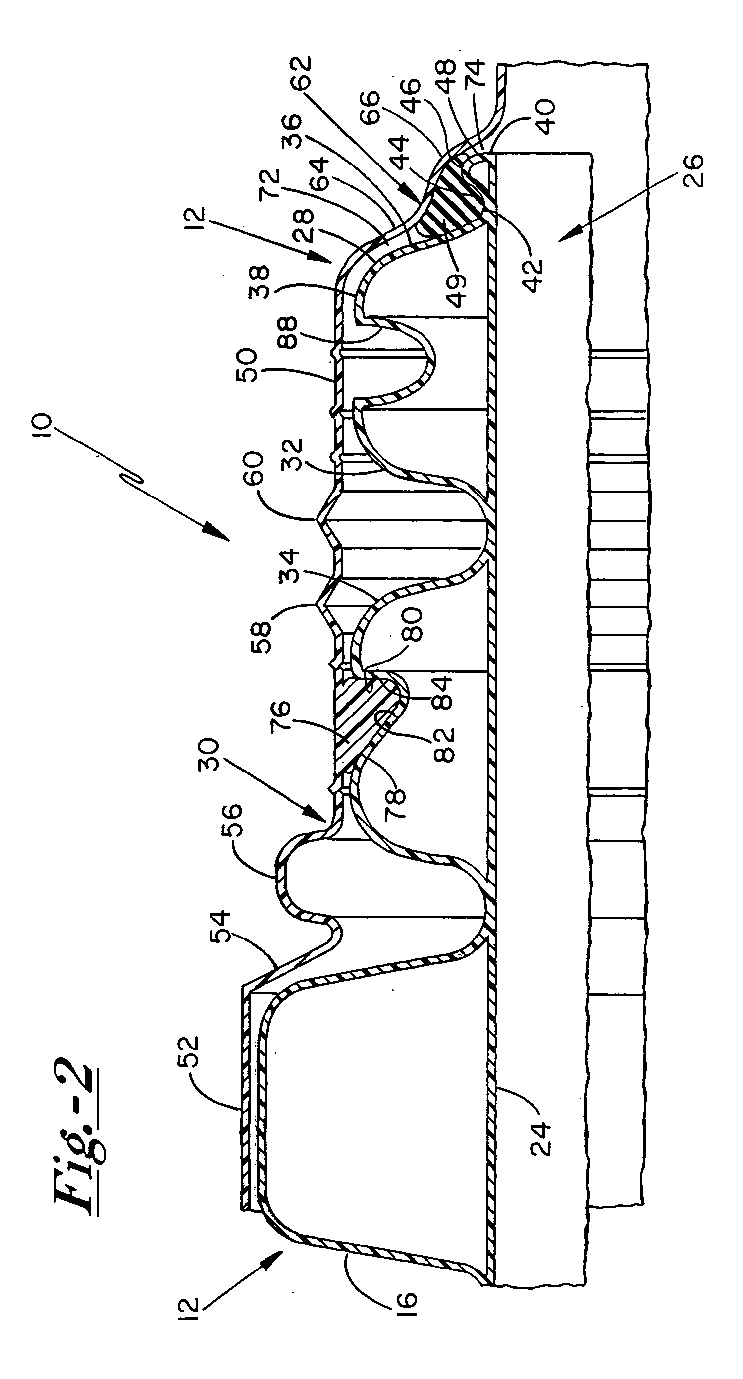
[0028] With reference to FIG. 1 of the drawings, an improved bell and spigot coupling system 10 is shown which is particularly well-suited for use in joining sections of corrugated plastic pipe 12 in gravity flow drainage and sewage applications requiring watertight joints. In accordance with the present invention, the adjoining sections of pipe 12 each have an outer corrugated sidewall 14 defined by spaced apart successive annular ribs 16 with annular valley defining portions 18 deposed therebetween. Each successive rib 16 is formed having a rib crest 20 and annular rib walls 22 which extend radially inward from the crest 20 to interconnect with and define the adjacent valley defining portions 18 of the sidewall 14. As shown best in FIG. 2, the corrugated pipe 12 is preferably of the dual wall type having an inner cylindrical smooth liner 24 that is attached to and integrally formed with the outer corrugated sidewall 14 at each of the valley defining portions 18 thereof.

[0029] In ...


PUM


Abstract

A bell and spigot coupling system is provided for joining corrugated plastic pipe which improves the coupling's sealing capability with increasing hydrostatic pressure, and causes a substantial component of the force generated therefrom to be absorbed axially through the coupled sections of adjoining pipe. The spigot end of one pipe which is received within a bell coupler for an adjoining pipe terminates in a small annular bed-forming rib which forms a gasket bed that holds a gasket compressed against a radially extending gasket sealing surface of the bell coupler. Inward protruding latches formed in the bell coupler engage the adjoining section of corrugated pipe to resist axial separation and hold the gasket compressed against the sealing surface of the bell coupler. The sealing surface of the bell coupler contours the spigot end of the adjoining pipe and forms radially constricting pathways at opposite sides of the gasket. The presence of either internal or external hydrostatic pressure on the coupling joint causes the gasket to wedge into one of the opposing radially constricted pathways, thus transferring the force generated by such pressure axially through the coupled sections of pipe.

Description

BACKGROUND OF THE INVENTION [0001] The present invention relates generally to the art of coupling systems for connecting tubing, pipe and the like. More specifically, the present invention has application to coupling systems for connecting corrugated plastic pipe used in watertight gravity-flow drainage and sewage applications, and particularly such type of pipe having a smooth interior wall for handling increased fluid flow capacity, as well as increased internal and external hydrostatic pressures. Although the present invention has particular relevance to the above applications, it will be appreciated that the principles of the present invention may also find application in other types of pipe and tubing configurations where watertight joints are deemed desirable. [0002] Under current standards established by the American Society of Testing and Materials (ASTM), it is required that corrugated polyethylene pipe intended for use in certain drain and gravity sewage applications achie...

Claims


Application Information

Patent Timeline
Patent Type & Authority Applications(United States)
IPC IPC(8): F16L17/00
CPCF16L25/0045F16L25/0054F16L25/0063Y10S285/903
Inventor DUININCK, JEREMY N.PLUIMER, MICHAEL L.
Owner PRINSCO
Why Eureka
Try Eureka