Remote controlled device for tool rotating

a remote control and tool technology, applied in mechanical control devices, manual control with single controlling member, toothed gearings, etc., can solve the problems of affecting the sterilisation of the tool, the loss of operation, and the inability to wash the flexible shaft or the flexible cable in the above mentioned arrangement, so as to achieve the effect of minimal loss

Inactive Publication Date: 2007-11-27
DUBROVSKY ARKADY VENIAMINOVICH
View PDF10 Cites 832 Cited by
  • Summary
  • Abstract
  • Description
  • Claims
  • Application Information

AI Technical Summary

Benefits of technology

[0014]It is accordingly one object of the present invention to provide a remote controlled device for tool rotating in which a construction of a link for transferring a working motion enables to transfer a motion with minimal losses.
[0015]Another object is to provide a remote controlled device for tool rotating which enables to make cleaning and sterilisation of the transferring link safe, reliable and cost-effective, as well as less labour-consuming than in the prior art devices. The present invention is intended to satisfy those needs.

Problems solved by technology

But in those devices due to the inherent elasticity characteristics of a flexible shaft the application of force in transferring a motion results in some losses in operation.
Furthermore, mechanic cleaning or washing the flexible shaft (as well as a flexible cable) from biological fragments and subsequent sterilisation thereof is substantially impeded.
The use of a flexible shaft or a cable which are not easy to wash and sterilise in the above mentioned arrangements is not advantageous.

Method used


Image

  • Remote controlled device for tool rotating
  • Remote controlled device for tool rotating
  • Remote controlled device for tool rotating

Examples


Embodiment Construction

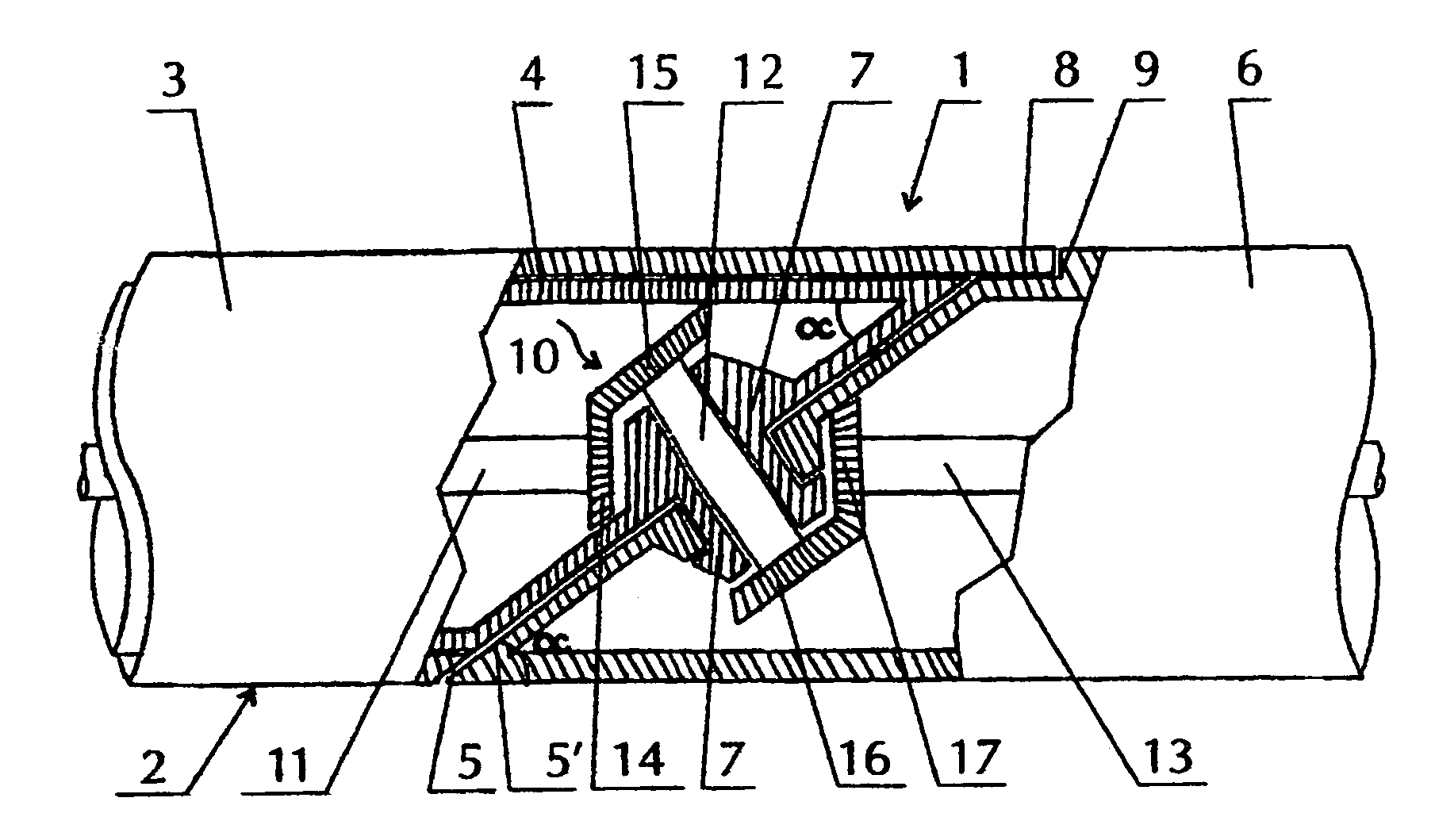
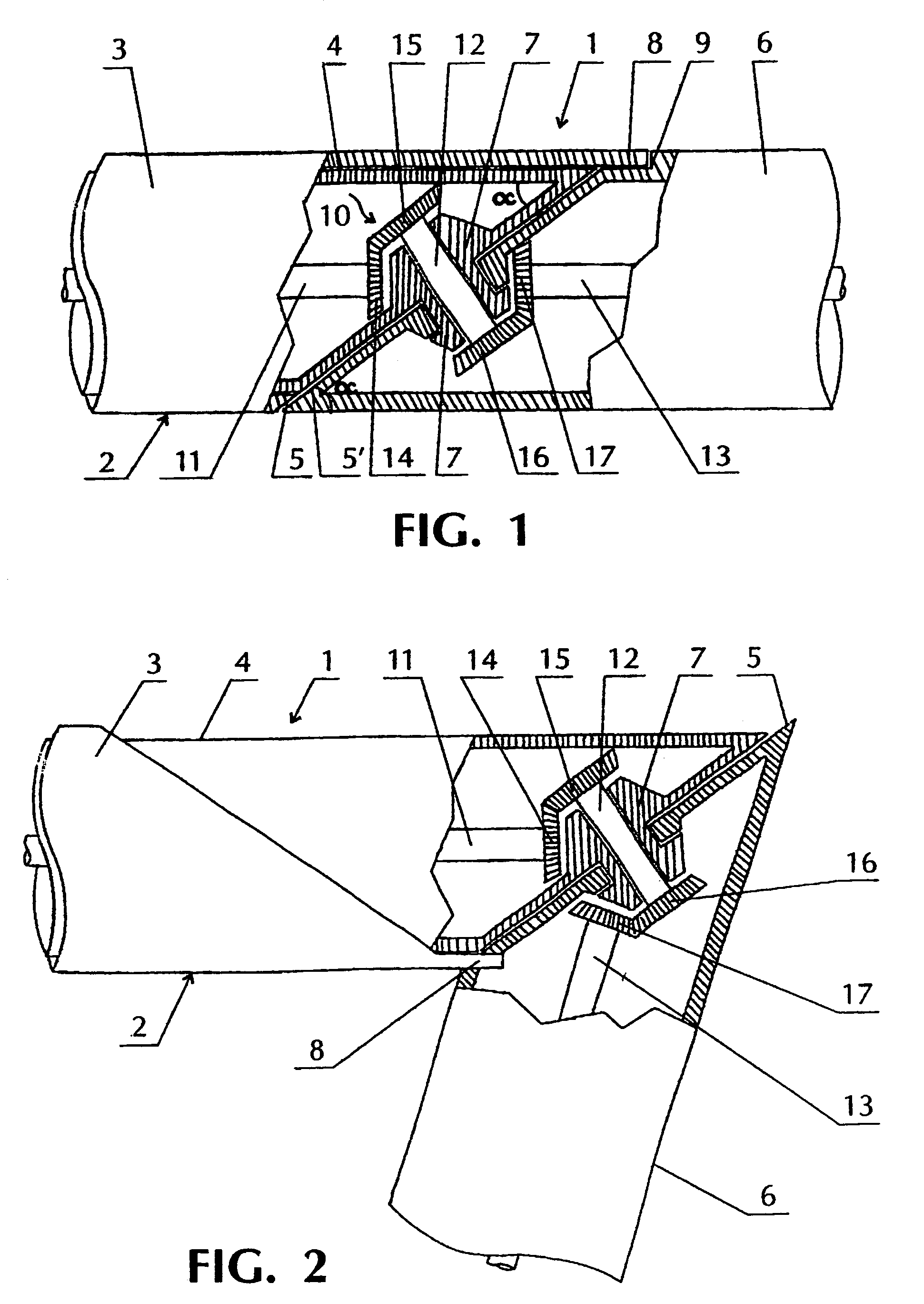
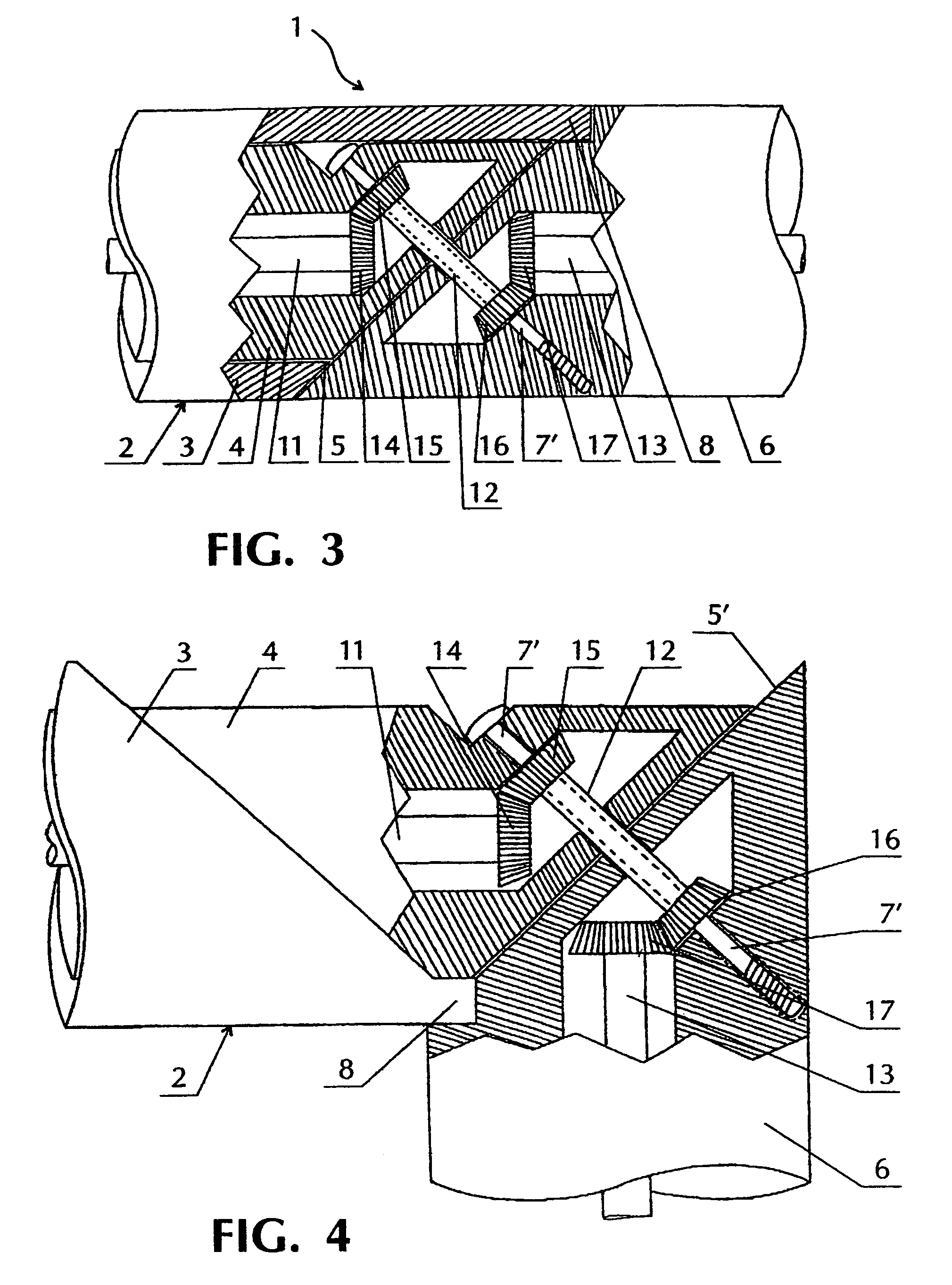
[0041]Reference is now made to FIGS. 1 and 2, wherein the remote controlled device for tool rotating comprises a body 1 which proximal part 2 formed by two co-axially arranged cylindrical elements 3 and 4 has a chamfered end surface 5 which is adjacent to and mated with a chamfered end surface 5′of the distal part 6. A hollow cylindrical axis 7 is mounted in the centre of the end surfaces chamfered at the same angle α and fixed at one of the chamfered end surfaces 5. The other chamfered end surface 5′ can freely rotate on the axis 7.

[0042]In the proximal part 2 the outer cylindrical element 3 has an eccentric rotation rod 8 intended to engage in a groove 9 of the distal part 6.

[0043]A link for transferring a working motion—a shaft 10 is arranged within the central channel of the device 1 and comprised of three sections: a driving section 11 of the shaft 10 located in the proximal part, a transmitting section 12 of the shaft 10 located within the central channel of the hollow axis 7 ...


PUM


Abstract

A remote-controlled device for rotating tools, preferably medical tools, comprising a hollow body (1) which is embodied in the form of pivotally connected proximal and distal parts (2, 6) provided with a pair of adjacent end surfaces (5, 5′) which are angularly disposed with respect to the longitudinal axis of the body (1), and an axis (7) which is perpendicularly oriented with respect to the end surfaces (5, 5′) and provided with a central channel and a remote control mechanism. A shaft (10) arranged in the central channel of the device comprises driven, driving and transmitting sections (11, 12, 13) respectively, and operates as a link for transferring working rotational motion at a variable angle. The tilt angle between the distal part (6) and the longitudinal axis of the proximal part (2) can be equal to 180°.

Description

FIELD OF INVENTION[0001]The present invention relates generally to instrument making field, namely, to a remote controlled device for tool rotating, more precisely, for medical tool rotating.DESCRIPTION OF RELATED ART[0002]Remote controlled devices for tool rotating that enable to adjust a tilt angle of the tool body with respect to the longitudinal axis are well known in the art. However, in almost all conventional devices a link for transferring a working motion from a control handle to a working unit employs a flexible tie (usually a cable) or a pusher.[0003]There have been proposed flexible rotating shafts for transferring a working motion to an operating unit of the device. But in those devices due to the inherent elasticity characteristics of a flexible shaft the application of force in transferring a motion results in some losses in operation. Furthermore, mechanic cleaning or washing the flexible shaft (as well as a flexible cable) from biological fragments and subsequent st...

Claims


Application Information

Patent Timeline
Patent Type & Authority Patents(United States)
IPC IPC(8): A61B17/00F16D3/00A61B17/28A61B17/32B23Q5/04F16H1/00F16H1/14G05G7/02
CPCA61B17/29A61B17/32002G05G7/02B23Q5/045F16H1/006A61B2017/2902A61B2017/2927F16H1/14A61B2017/320032
Inventor DUBROVSKY, ARKADY VENIAMINOVICH
Owner DUBROVSKY ARKADY VENIAMINOVICH
Why Eureka
Try Eureka