Enforcing computer security utilizing an adaptive lattice mechanism

a technology of adaptive lattice and computer security, applied in the field of computer and information security, can solve problems such as limitations to such an approach, system security not based on security, and control of access to information and computer system resources is a continuing problem

Active Publication Date: 2007-11-27
LIONRA TECH LTD
View PDF17 Cites 12 Cited by
  • Summary
  • Abstract
  • Description
  • Claims
  • Application Information

AI Technical Summary

Benefits of technology

[0016]FIG. 4A is an example of a process / user access table.

Problems solved by technology

Control of access to information and computer system resources is a continuing problem for system, database, and network administrators across the government, military, and private industry.
However, there are a number of serious limitations to such an approach, primarily because control over information access is limited to a simple relational comparison.
Significantly, such systems do not enforce security based on patterns of behavior, aggregation of data, or information clustering.
Further, conventional systems make use of simple point tests which do not support the ability to look at temporal patterns of access.
This patent focuses on flagging suspicious activity but does not address enforcement of a security policy based on such flagging.

Method used


Image

  • Enforcing computer security utilizing an adaptive lattice mechanism
  • Enforcing computer security utilizing an adaptive lattice mechanism
  • Enforcing computer security utilizing an adaptive lattice mechanism

Examples


example 1

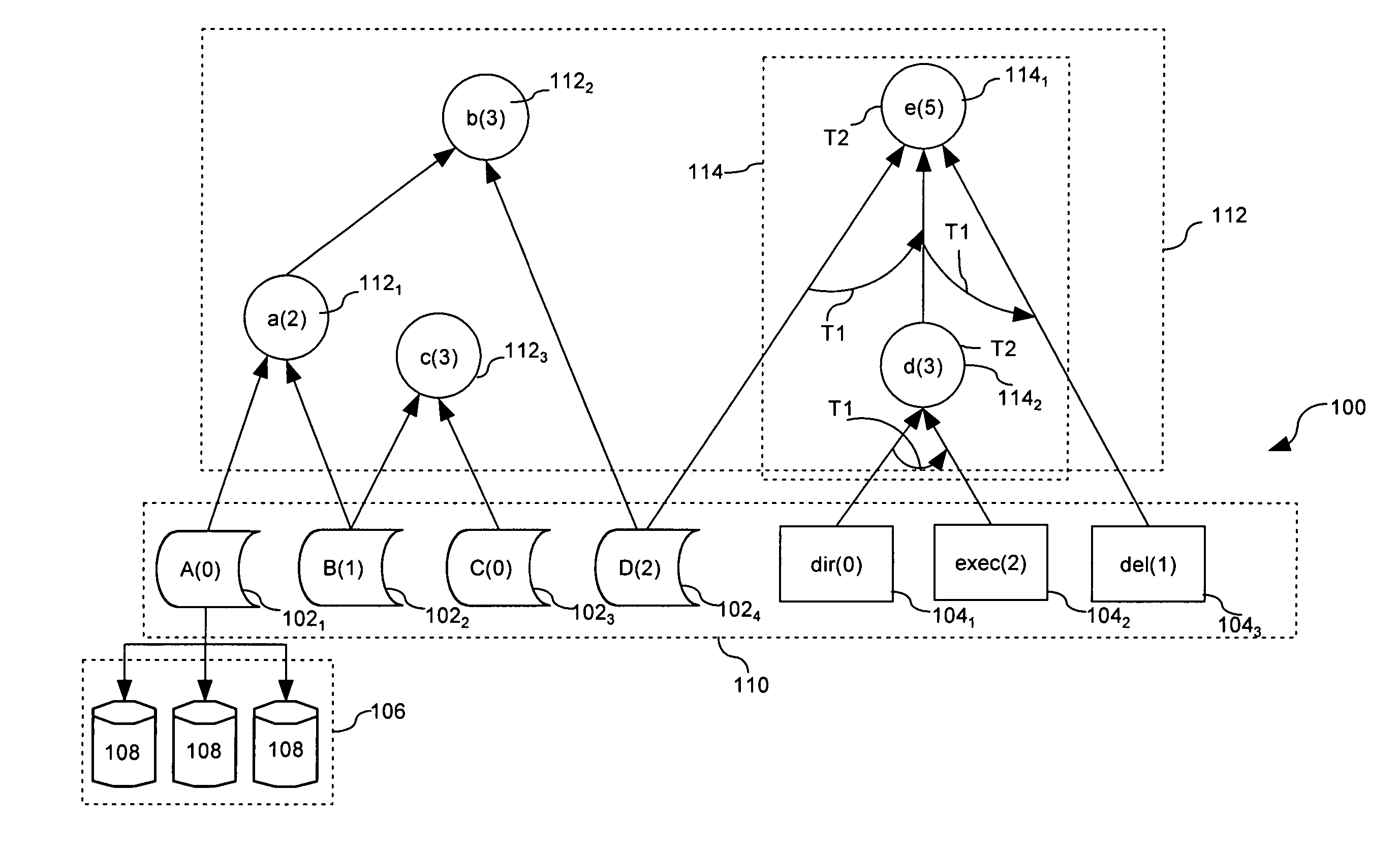
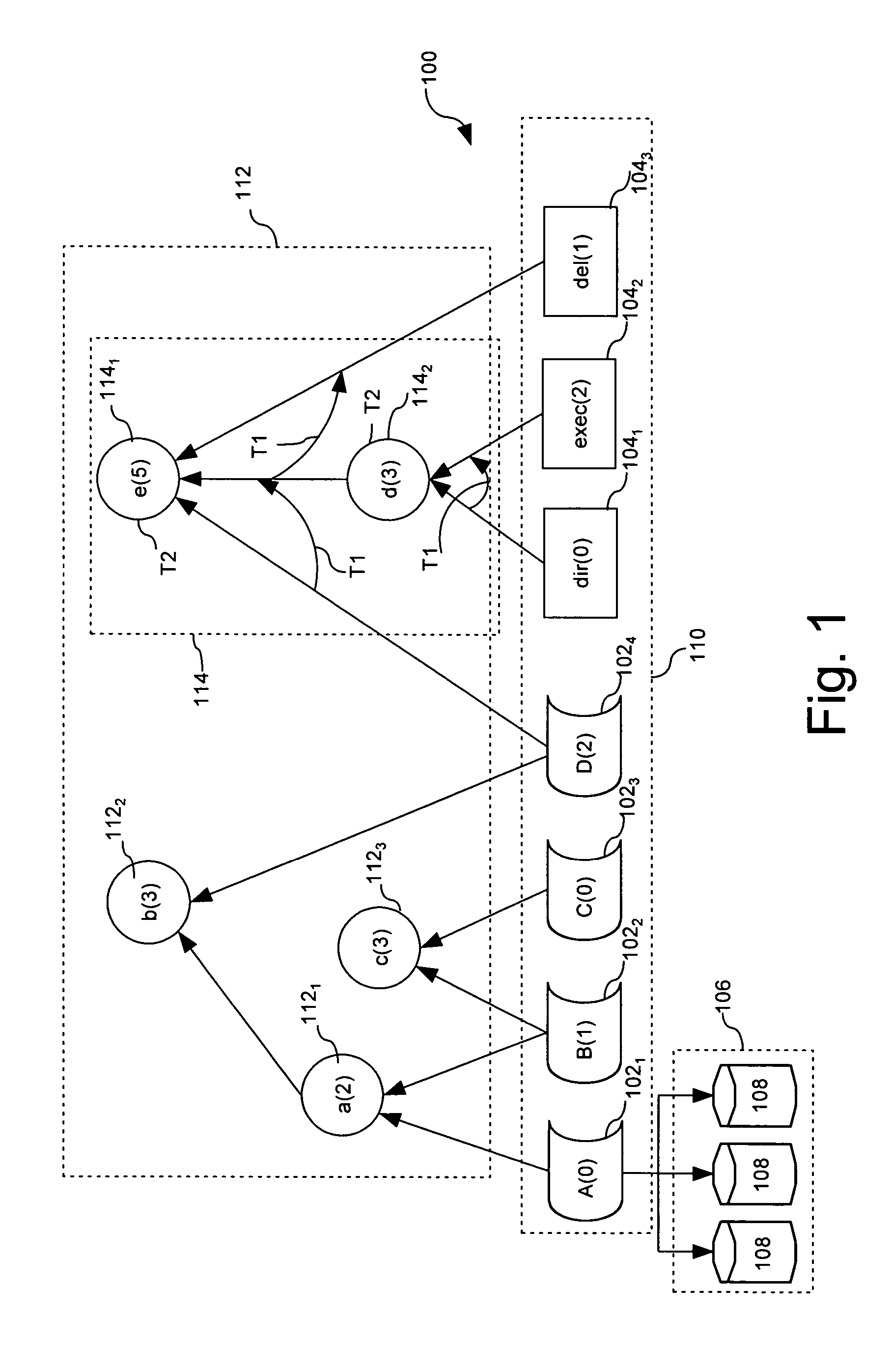
[0041]Referring to FIGS. 1 and 8, consider the case in which access authorization for users 1-5 is established in accordance with PUAT in FIG. 8A. User 2 with access level 1, U2(1) can request access to an object 1021 of information type A as previously described in relation to step 604. In accordance with step 606, the system consults the TOT (Temporal Order Table) in FIG. 8B and determined that the access request time does not complete a temporal access pattern. Subsequently, the request is logged in the (Temporal Access Table) as provided in step 610. In accordance with step 612 the request is tested to determine if user 2 has a sufficiently high level of access authorization. In this case U2(1)≧A(0) and therefore access is granted to the requested information type A in accordance with step 616.

[0042]Thereafter, in step 702 the computer system can identify aggregations with object A using the CCT (Combinatorial Classification Table) in FIG. 8C. In step 704, the system checks to d...

example 2

[0046]Referring to FIGS. 1 and 9, consider the case in which access authorization for users 1-5 is established in accordance with PUAT in FIG. 9A. User 3 with access level 2, U3(2) can request access to an object 102, of information type A as previously described in relation to step 604. In accordance with step 606, the system consults the TOT (Temporal Order Table) in FIG. 9B and determined that the access request time does not complete a temporal access pattern. Subsequently, the request is logged as provided in step 610. In accordance with step 612 the request is tested to determine if User 3 has a sufficiently high level of access authorization. In this case U3(2)≧A(0) and therefore access is granted to the requested object 102, in accordance with step 616.

[0047]Thereafter, in step 702 the computer system can identify aggregations with object A using the CCT (Combinatorial Classification Table) in FIG. 9C. In step 704, the system checks to determine if the minimum required secur...


PUM


Abstract

Method and apparatus for ensuring secure access to a computer system (1000). The method can begin with the step of receiving in the computer system a request from an entity (using 1002). The entity can have a predetermined access authorization level for access to a first base node (110) representing an information type (102) or a computer system function (104). The system determines if the access request completes a prohibited temporal access pattern for the entity. The system also compares a minimum access level established for the first base node to the predetermined access authorization level assigned to the entity. Thereafter, the system can grant the access request only if the minimum access level for the first base node does not exceed to the predetermined access authorization level.

Description

BACKGROUND OF THE INVENTION[0001]1. Statement of the Technical Field[0002]The inventive arrangements relate generally to computer and information security and more particularly to security measures that enforce security based on logical implementation methods.[0003]2. Description of the Related Art[0004]Control of access to information and computer system resources is a continuing problem for system, database, and network administrators across the government, military, and private industry. Providing system security in such multi-user environments requires a balance between permitting access to resources necessary to perform the business functions for the enterprise and limiting access. Current security methods fall within two basic categories. These include physical and logical implementation methods.[0005]Methods for implementing logical security safeguards typically provide access based on a user / group / role identifier and an access control list for the file, database, or system f...

Claims


Application Information

Patent Timeline
Patent Type & Authority Patents(United States)
IPC IPC(8): G06F7/04G06F12/14G06F21/62
CPCG06F21/6227G06F2221/2145G06F2221/2141G06F2221/2113
Inventor KOVARIK, JR., VINCENT JOSEPH
Owner LIONRA TECH LTD
Why Eureka
Try Eureka