Gear change mechanism

a technology of gear change mechanism and gear lever, which is applied in the direction of gearing, mechanical actuated clutches, interengaging clutches, etc., can solve the problem of significant space occupation

Active Publication Date: 2007-12-04
QINETIQ LTD
View PDF15 Cites 1081 Cited by
  • Summary
  • Abstract
  • Description
  • Claims
  • Application Information

AI Technical Summary

Benefits of technology

[0005]The present invention seeks to provide a gear change mechanism operating on the dog clutch prin

Problems solved by technology

This is a simple, robust and effective mechanism but necessarily occupies significant space in the axial direction due to the spacing of the

Method used


Image

  • Gear change mechanism
  • Gear change mechanism
  • Gear change mechanism

Examples


Embodiment Construction

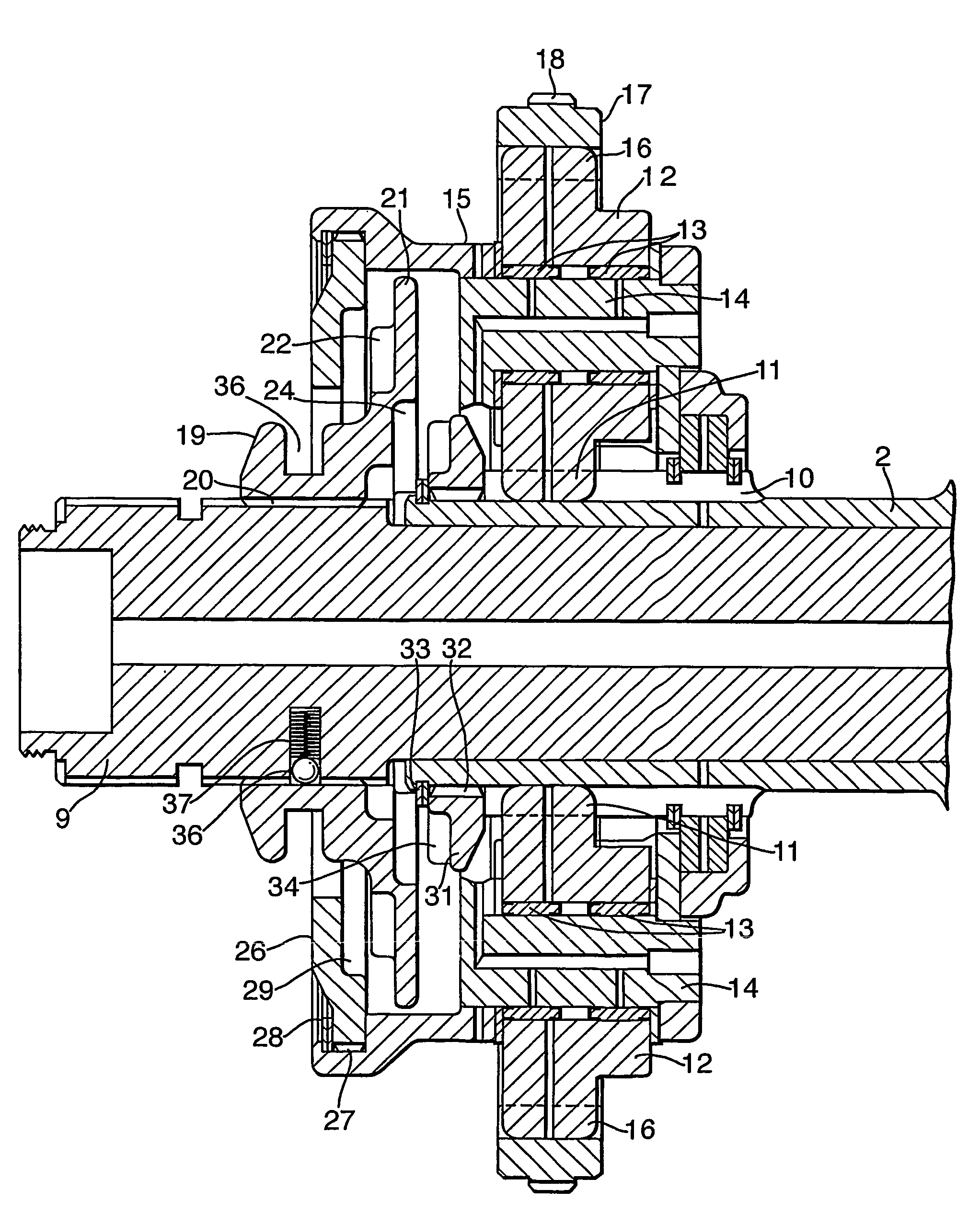
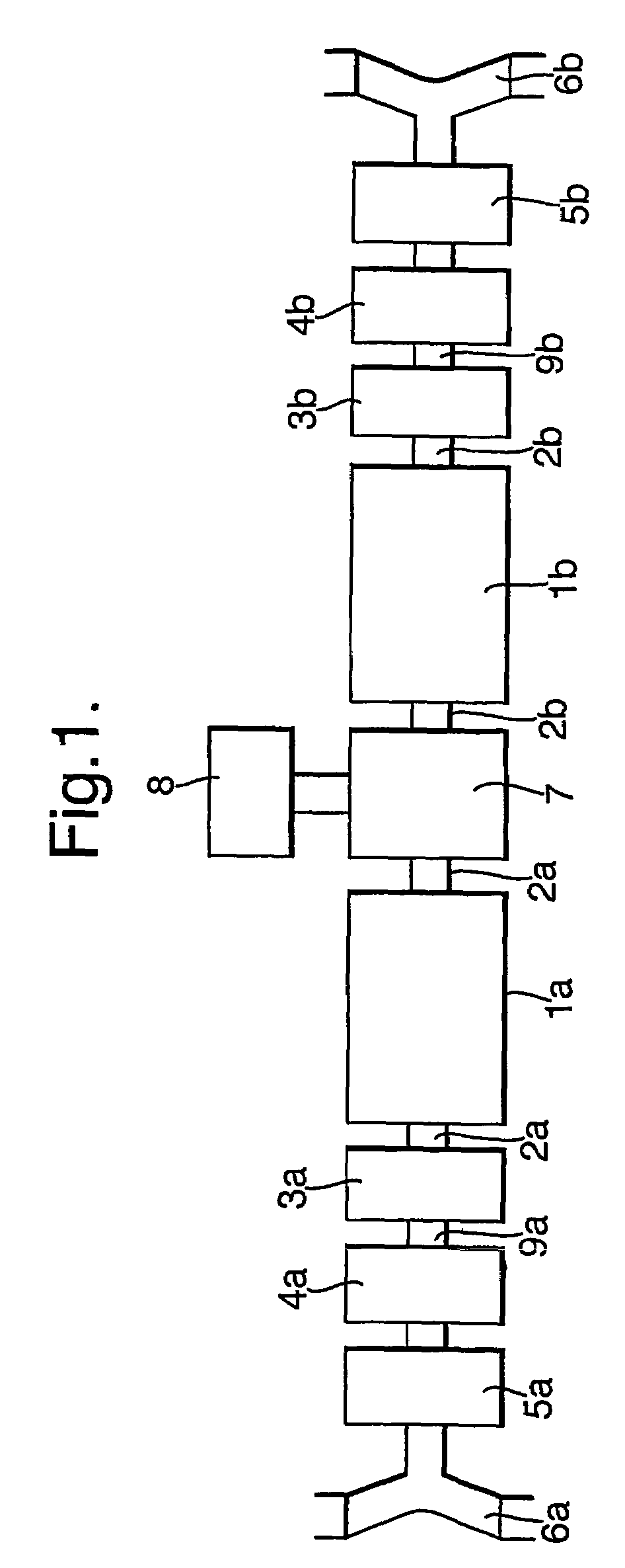
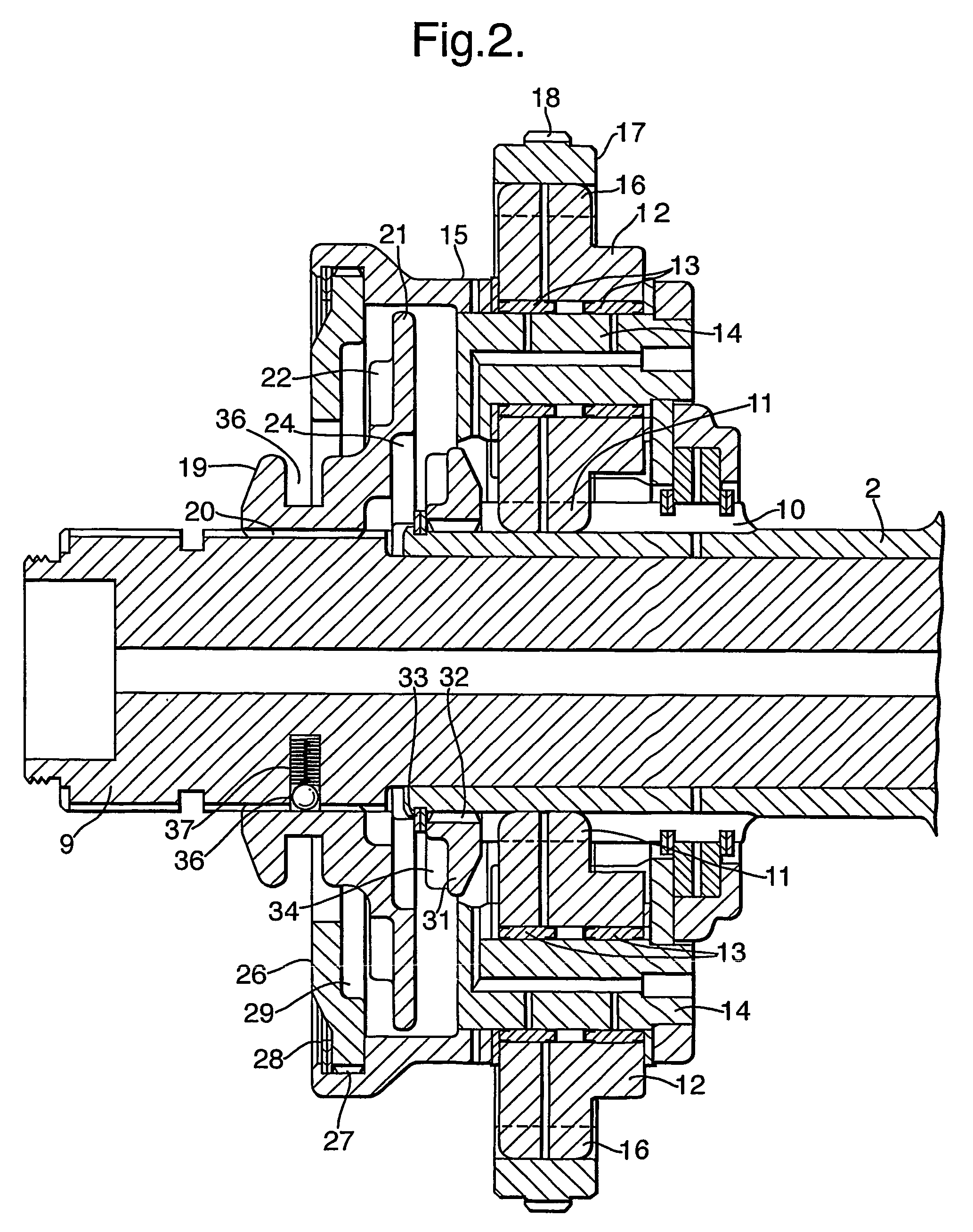
[0016]FIG. 1 illustrates diagrammatically one form of drive configuration with which gear change mechanisms in accordance with the present invention may be found particularly useful, being a track drive arrangement for a skid steered vehicle according to WO-02 / 083483. It is to be understood, however, that the present mechanisms are more generally applicable to gear change functions in vehicles or other machinery, particularly where an axially compact mechanism is required.

[0017]In FIG. 1 a transverse drive arrangement comprises two electric propulsion motors 1a and 1b turning drive shafts 2a and 2b. Outboard of the motors the transmission includes in each case a gear change unit 3a, 3b brake 4a, 4b and final drive gear reduction 5a, 5b, all encased within the vehicle hull, leading to respective track drive sprockets 6a and 6b at opposite sides of the vehicle. Inboard the motor shafts 2a and 2b are coupled to a controlled differential 7 driven by an electric steer motor 8, all as des...


PUM


Abstract

A gear change mechanism coupling a pair of shafts employs a planetary gear set comprising a sun gear fast with a first of the shafts, planet gears in a planet carrier, and an annulus or ring gear, the latter being fixed. A selector hub slidable on the other of the shafts has sets of radially spaced dogs to engage with corresponding dogs on the planet carrier and sun gear respectively, so as to couple the shafts at two different ratios depending on the axial position of the selector hub. This results in a more axially compact package than conventional dog clutch gear changers. In an alternative embodiment a reversing mechanism is provided by fixing the planet carrier and engaging the selector hub with the sun gear or annulus depending on its axial position.

Description

BACKGROUND OF THE INVENTION[0001](1) Field of the Invention[0002]The present invention relates to gear change mechanisms and more particularly to such mechanisms employing dog clutches. Mechanisms according to the invention may be found useful in a variety of vehicular applications or in other machinery where a simple, robust and compact gearbox is required, one particular application being for a battle tank, bulldozer or other skid steered vehicle equipped with a drive configuration as described in WO-02 / 083483.[0003](2) Description of the Art[0004]Constant-mesh gearboxes commonly employ dog clutches in the selection of different gear ratios. In a typical arrangement a gear selector hub is splined on an output shaft with freedom to slide axially along the shaft but so that the shaft must always rotate with the selector hub. Gears driven by the engine or other prime mover at different ratios are located coaxially to either side of the selector hub. The confronting faces of the selec...

Claims


Application Information

Patent Timeline
IPC IPC(8): F16H3/44F16D11/14F16H3/54
CPCF16H3/54
Inventor THOMPSON, ROBERT WILLIAM
Owner QINETIQ LTD
Why Eureka
Try Eureka