
Broadcast width and location control for a combine spreader

a spreader and combine technology, applied in the direction of agriculture tools and machines, ways, centrifugal wheel fertilisers, etc., can solve the problem of unfavorable broadcast coverage, and achieve the effect of constant spreader broadcast width and location

Active Publication Date: 2007-12-11
DEERE & CO
View PDF21 Cites 51 Cited by
  • Summary
  • Abstract
  • Description
  • Claims
  • Application Information

AI Technical Summary

Problems solved by technology

All of these conditions can result in uneven broadcast coverage of MOG over a harvested field, which is undesirable.

Method used


Image

  • Broadcast width and location control for a combine spreader
  • Broadcast width and location control for a combine spreader
  • Broadcast width and location control for a combine spreader

Examples


first embodiment

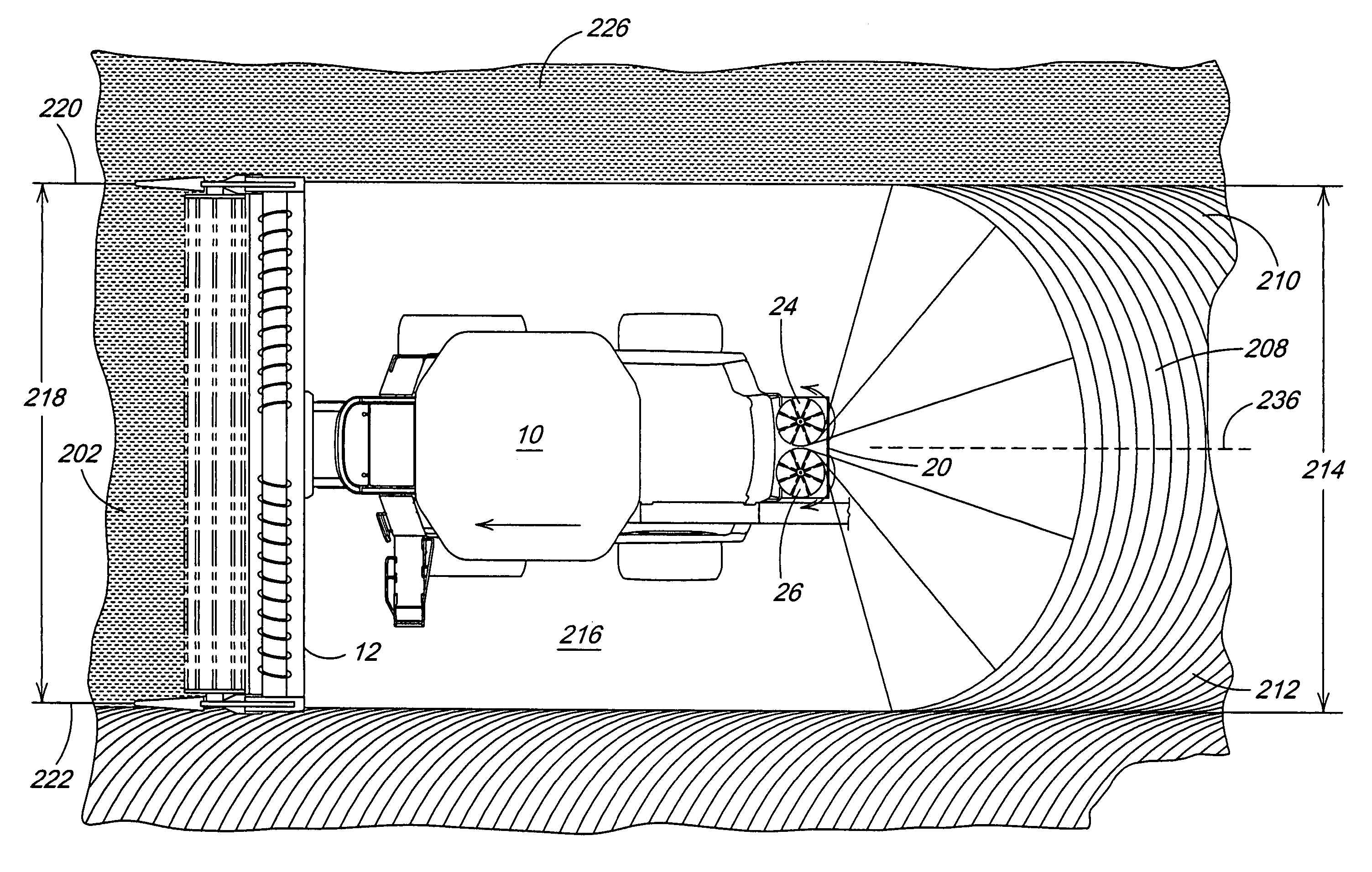
[0020]The present invention provides an effective means of maintaining a constant spreader broadcast width 214 and location 236 by controlling impeller 24 and 26 rotational speeds. In a first embodiment illustrated in FIGS. 7 and 8, the impeller 24 and 26 rotational speeds are varied manually by an operator to maintain a desired broadcast width 214 and location 236. The broadcast width 214 may be any width desired by the operator, or for example, may correspond to the header cutting width 218. This embodiment requires at least one command input device 100 to command impeller 24 and 26 speeds, and a circuit 110 to control impeller 24 and 26 speeds. The impeller 24 and 26 rotational speeds may be controlled either individually, or in an alternate embodiment, in tandem with an inverse speed differential between the impellers 24 and 26. The command input devices 100 could be mechanical valves, electrical dials or digital toggles. The input devices 100 could be used to directly command t...

second embodiment

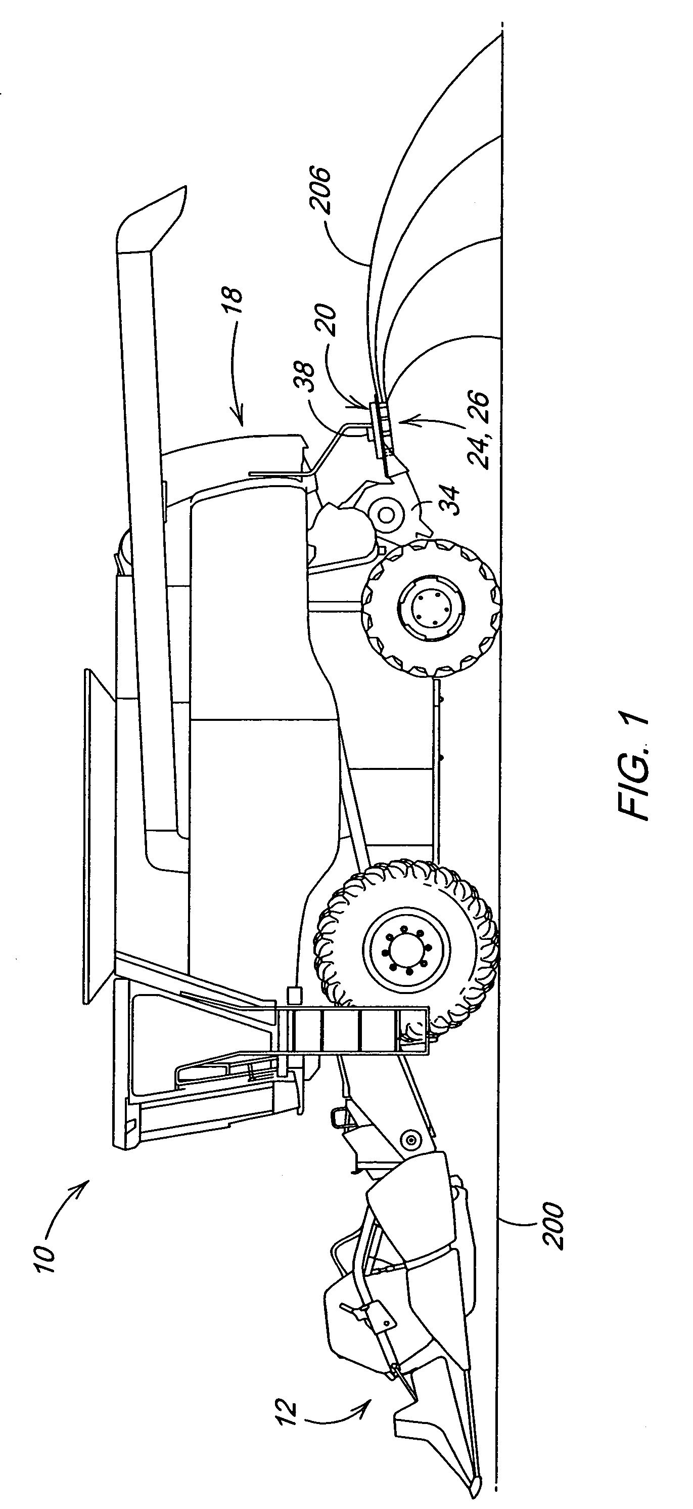
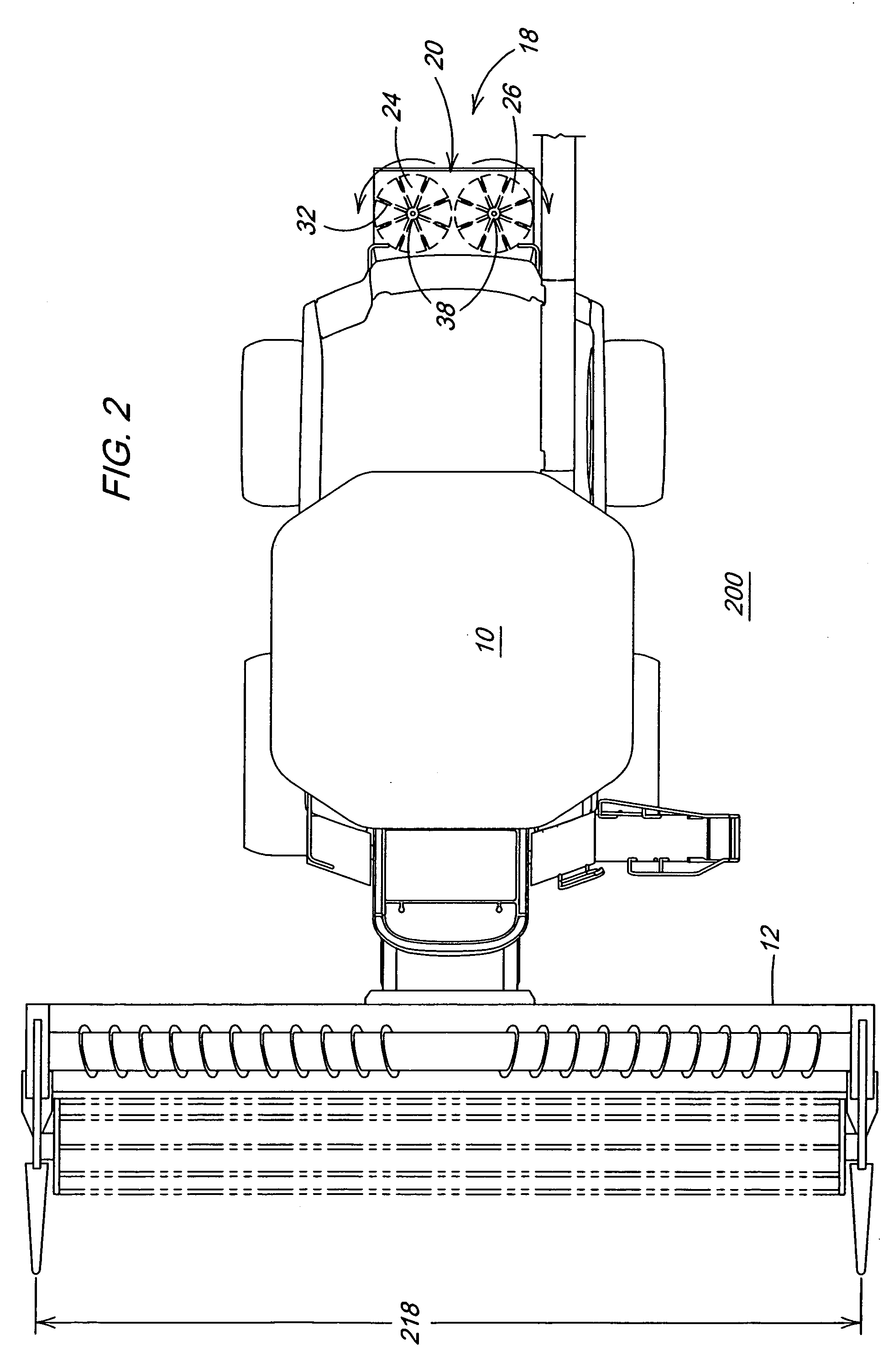
[0023]FIG. 9 illustrates the present invention, wherein the impeller 24 and 26 rotational speeds are varied automatically to maintain a desired broadcast width 214 and location 236 by a control system that directly monitors broadcast MOG 206. This embodiment requires one or more sensor input devices 120 and 122 to sense broadcast width 214, a controller 130 to command impeller 24 and 26 speed based on sensor information, and a circuit 110′ like those described above to control impeller 24 and 26 speed. The sensors 120 and 122 in this embodiment may be electromagnetic (laser) or acoustical (sonar) sensors. The circuit 110 controlling impeller 24 and 26 speed would most likely be electro-hydraulic for hydraulic driven impellers 24 and 26, but could also be electrical in the case of electric motor driven impellers. This embodiment is a relatively simple system, since it involves a closed-loop sensor feedback that does not require computational adjustments from the controller 130.

[0024]...


PUM


Abstract

A work vehicle having a fluent material spreader comprising two counter-rotating variable speed impellers adapted to receive and broadcast fluent material. A right-side impeller broadcasts out to a right-side material broadcast width, and left-side impeller broadcasts out to a left-side material broadcast width. Rotational speed of the right-side impeller is commanded to achieve a desired a right-side material broadcast width, and rotational speed of the left-side impeller is commanded to achieve a desired a left-side material broadcast width. Command of the right-side and left-side impellers is achieved either manually by and operator, or automatically by a control system based on sensor input.

Description

FIELD OF THE INVENTION[0001]The present invention relates to control of a rotating material spreader, and more specifically, broadcast width and location control for an impeller-type material spreader of an agricultural combine.BACKGROUND OF THE INVENTION[0002]A combine is a machine that is used in grain farming to harvest a variety of crops from a field. Combines are typically self-propelled, but some are also towed and powered by tractors. As a combine moves through a field during a harvesting operation, the ripened crop is cut from the field by a header at the front of the combine. The crop is then transferred into threshing and separating assemblies within the combine, where grain is removed from the crop material. Crop material other than grain (MOG) is expelled from rear of the combine.[0003]An impeller-type spreader is an assembly attached to the rear of the combine that is adapted to receive MOG expelled from the combine and evenly broadcast it over a wide area of ground beh...

Claims


Application Information

Patent Timeline
Patent Type & Authority Patents(United States)
IPC IPC(8): A01C15/00A01D41/12A01F12/40
CPCA01F12/40A01D41/1243
Inventor PEARSON, MARK LEONARDMACKIN, RYAN PATRICK
Owner DEERE & CO
Learn More