

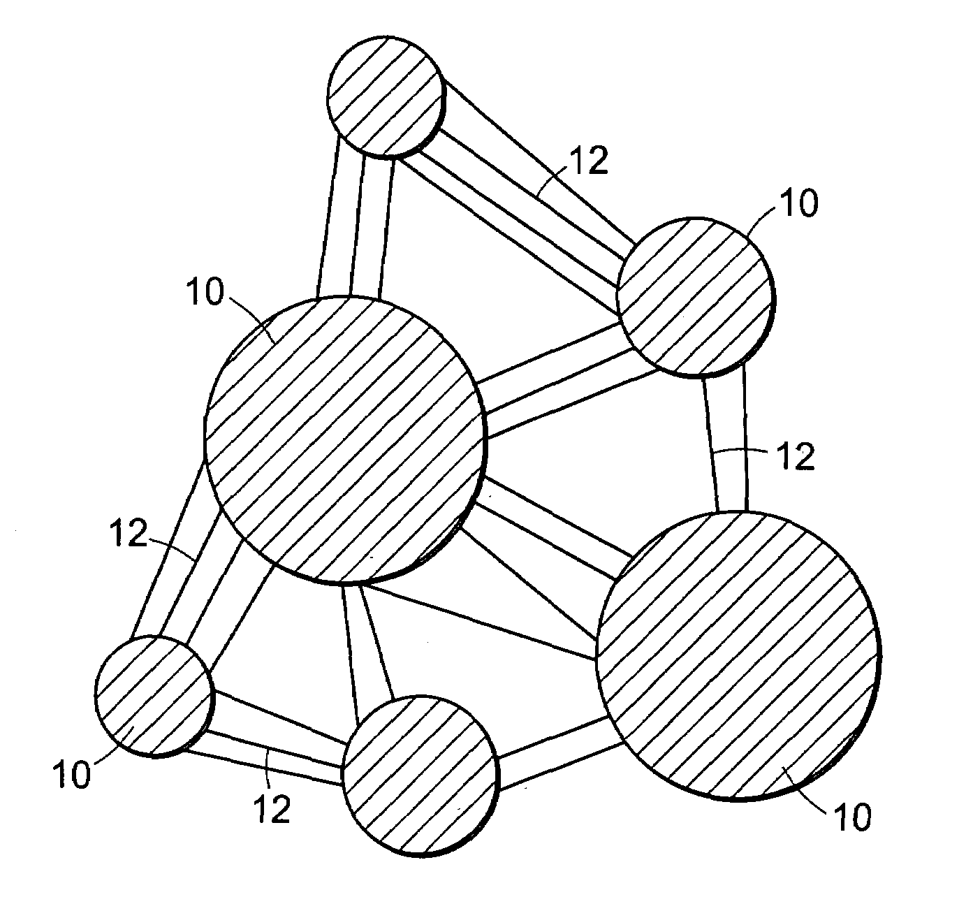
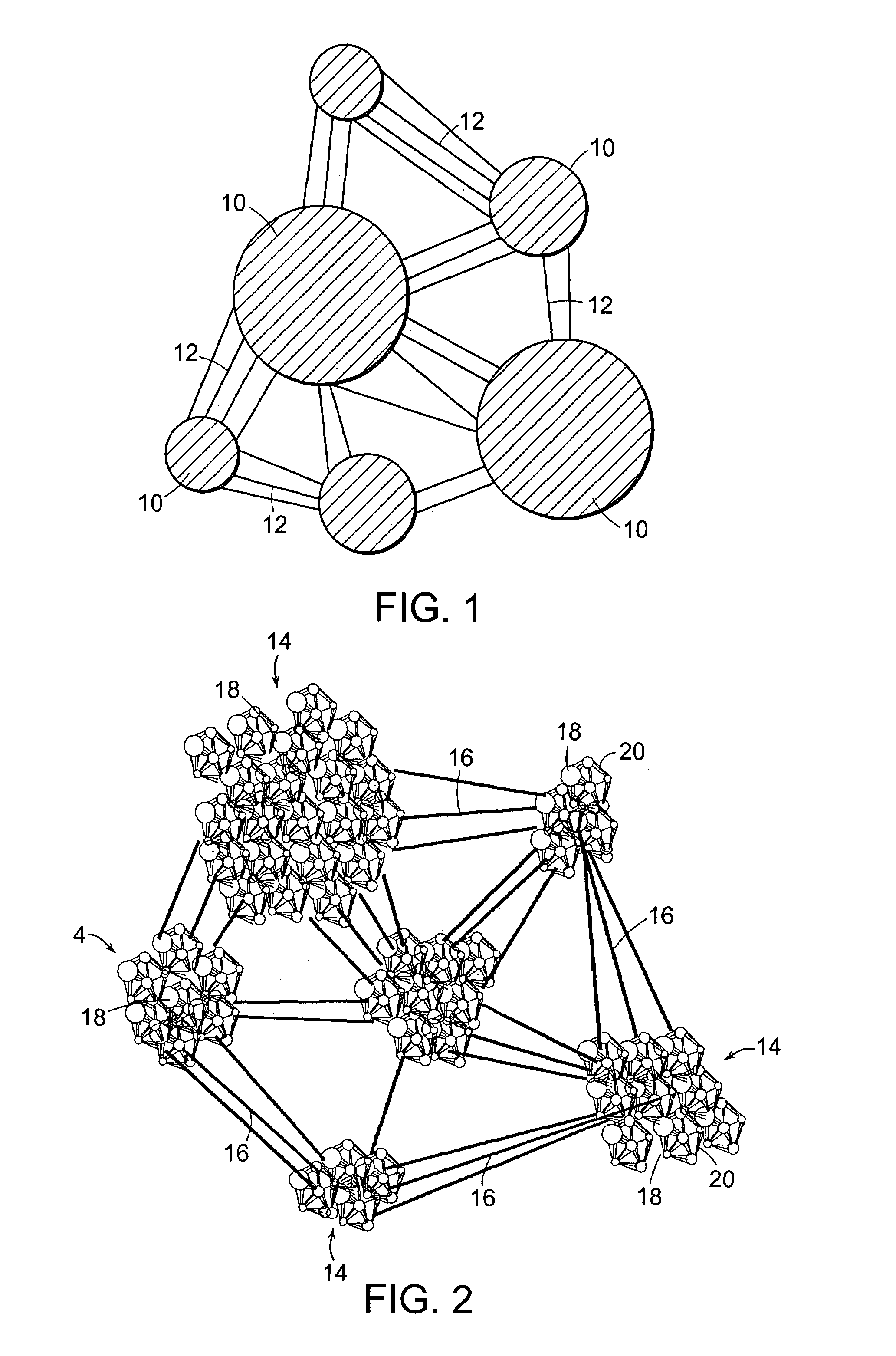
PTFE material with aggregations of nodes
a technology of ptfe and nodes, applied in the field of composite articles, can solve problems such as unsatisfactory solutions to this technical problem, and achieve the effect of asymmetric microstructur
- Summary
- Abstract
- Description
- Claims
- Application Information
AI Technical Summary
Benefits of technology
Problems solved by technology
Method used
Image

Examples
example 1
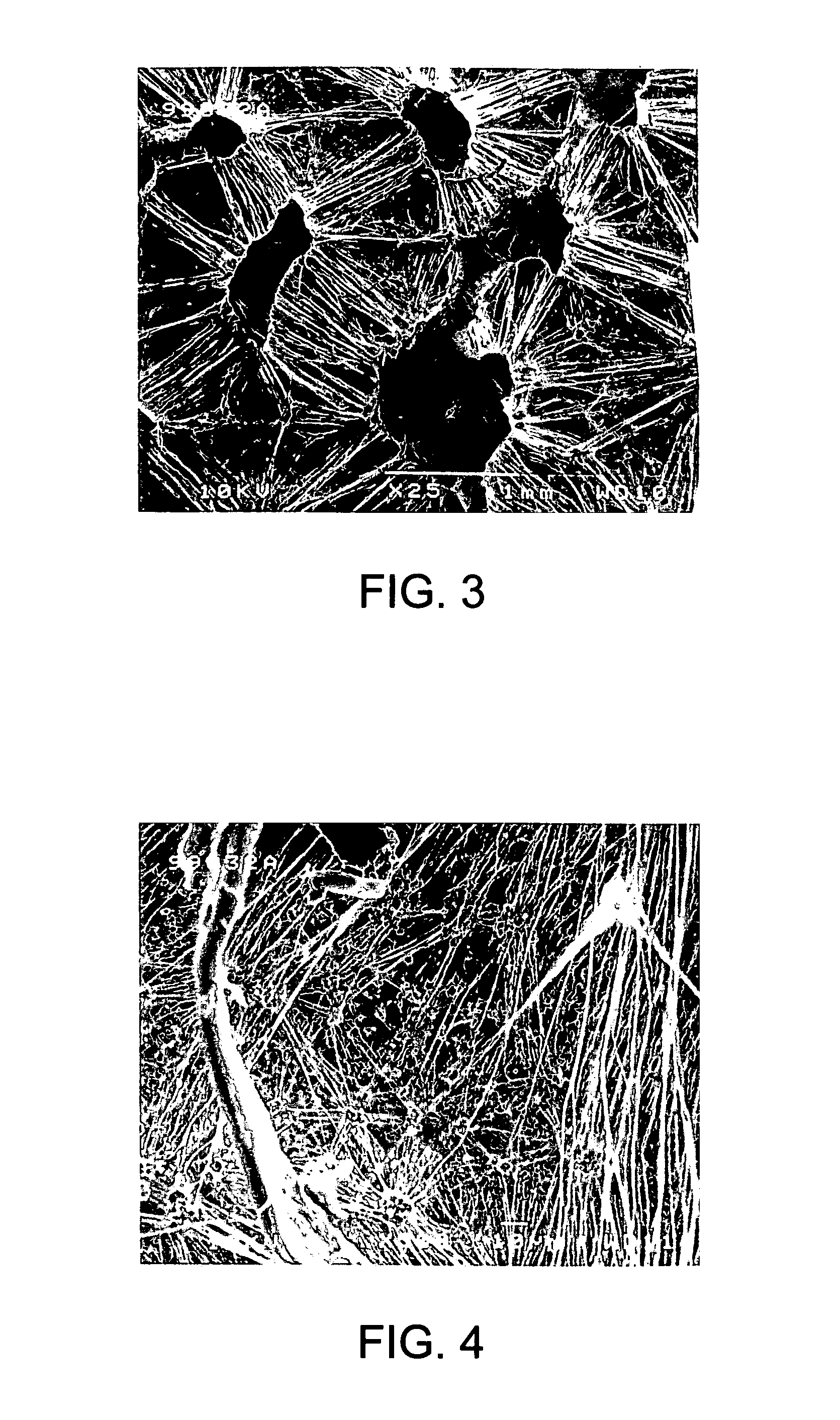
[0037]A PTFE resin was blended with a typical amount of mineral spirits (about 100 cc per pound of resin) to form a paste, and the paste was billeted, extruded and calendered in a conventional manner to make a tape of the type H PTFE component. The type H PTFE tape was then stacked into 10 layers, and the stack was calendered to a final thickness of about 0.1 inches. The multi-layered sheet resulting from the calendering step was dried in an oven to remove the mineral spirits, and dried. Thereafter, the dried sheet was radially expanded at an expansion ratio of about 5:1 and at an expansion rate of about 200% / second. The resulting first ePTFE article was sintered above the crystalline melt temperature of the PTFE to “lock” the structure.
[0038]A PTFE resin was blended with a high amount of mineral spirits (about 200 cc per pound of resin) and the paste was billeted, extruded, and calendered in a conventional manner to make a tape of the type L PTFE component. The type L PTFE tape was...
PUM
| Property | Measurement | Unit |
|---|---|---|
| length | aaaaa | aaaaa |
| length | aaaaa | aaaaa |
| length | aaaaa | aaaaa |
Abstract
Description
Claims
Application Information