Process for operating a discharge lamp

a discharge lamp and process technology, applied in process and machine control, electric variable regulation, instruments, etc., can solve problems such as unnecessary losses in the circuit, and achieve the effect of improving the ballast functioning

Inactive Publication Date: 2007-12-11
ELTAM EIN HASHOFET
View PDF6 Cites 12 Cited by
  • Summary
  • Abstract
  • Description
  • Claims
  • Application Information

AI Technical Summary

Benefits of technology

[0003]It is therefore a broad object of the present invention to ameliorate the disadvantages of the prior art electronic ballasts, and to provide a process for operating HID lamps that improves the ballast functioning.
[0004]It is a further object of the present invention to provide a process for operating HID lamps that secures ignition, glow-to-arc transition and efficient control of the lamp's transient High-current / Low-voltage phase and normal operation thereafter.
[0005]It is still a further object of the present invention to provide ballast protection and to lower ballast losses, EMI generation and circuit cost.
[0008]A still further aspect of the invention is that load current sensing is performed by a simple current peak-detector, thus providing low measurement noise and a current sensing resistor having minimum value and minimum losses.
[0009]Still further, according to the invention the operation of the PFC comprises boost and modified-boost modes, both critically discontinuous. The boost mode is achieved with the buck switch continuously conducting and the boost switch operating at high frequency. When the input AC instantaneous voltage approaches the value of the output DC voltage, a “watchdog” timer is activated in the control circuit of the buck switch to block said switch when the inductor's discharge duration becomes too long, say, twice the charge time. Consequently, the inductor discharge is substantially accelerated and appropriate operating frequency is maintained. When the inductor current has discharged, both switches begin conduction thus initiating a new cycle of discharge-time-limited boost (modified boost). The modified-boost mode during the phase in which the input AC voltage value is between 70 to 130% of the value of the output DC voltage, improves the efficiency of the circuit and smoothes the transitions between the modes.

Problems solved by technology

Consequently, unnecessary losses are developed in the circuit, specifically, but not exclusively, during the lamp's initial transient phase that follows the ignition of the arc while the lamp's voltage is low and its current is high.

Method used


Image

  • Process for operating a discharge lamp
  • Process for operating a discharge lamp
  • Process for operating a discharge lamp

Examples


Embodiment Construction

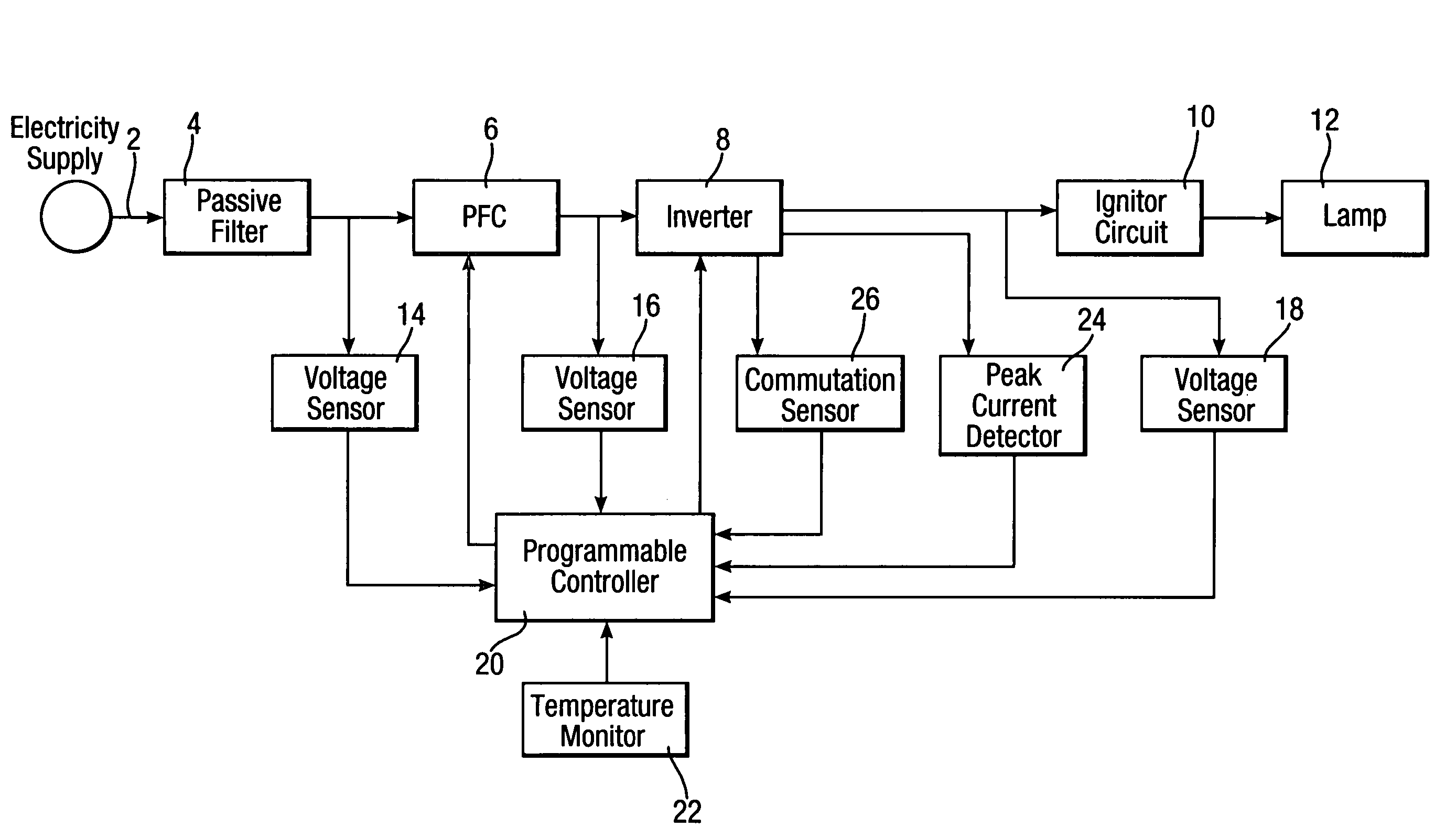
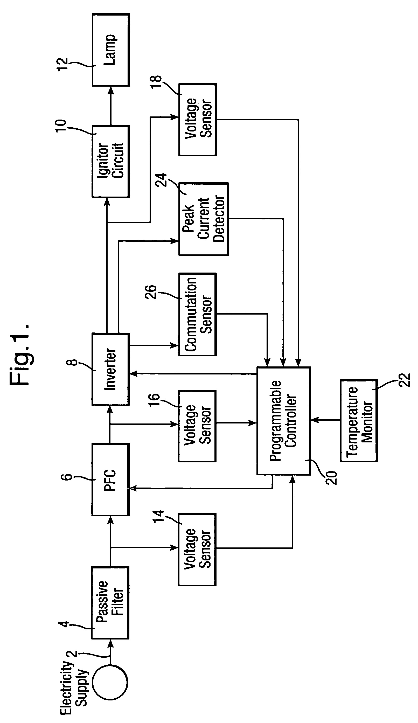
[0022]In FIG. 1 there is illustrated a block diagram of an embodiment of a programmable ballast for the implementation of the present invention. The electrical energy flows from an electricity supply via line 2 through a passive filter 4, a PFC stage 6, an inverter 8 and an ignitor circuit 10 into an HID lamp 12. Three voltage sensors 14, 16 and 18 are provided that sense the PFC input voltage, its output voltage and the lamp voltage, respectively, and deliver the respective voltage data to a programmable controller 20. Also provided is a temperature monitor 22 that delivers to the controller 20 data relating to the circuit temperature, thereby enabling the controller 20 to prevent excessive temperatures in the ballast, by reducing the power delivered through the circuit to the lamp 12. Lamp current is sensed and monitored through a peak-current-detector 24 provided in the inverter 8. Also seen is a commutation sensor 26.

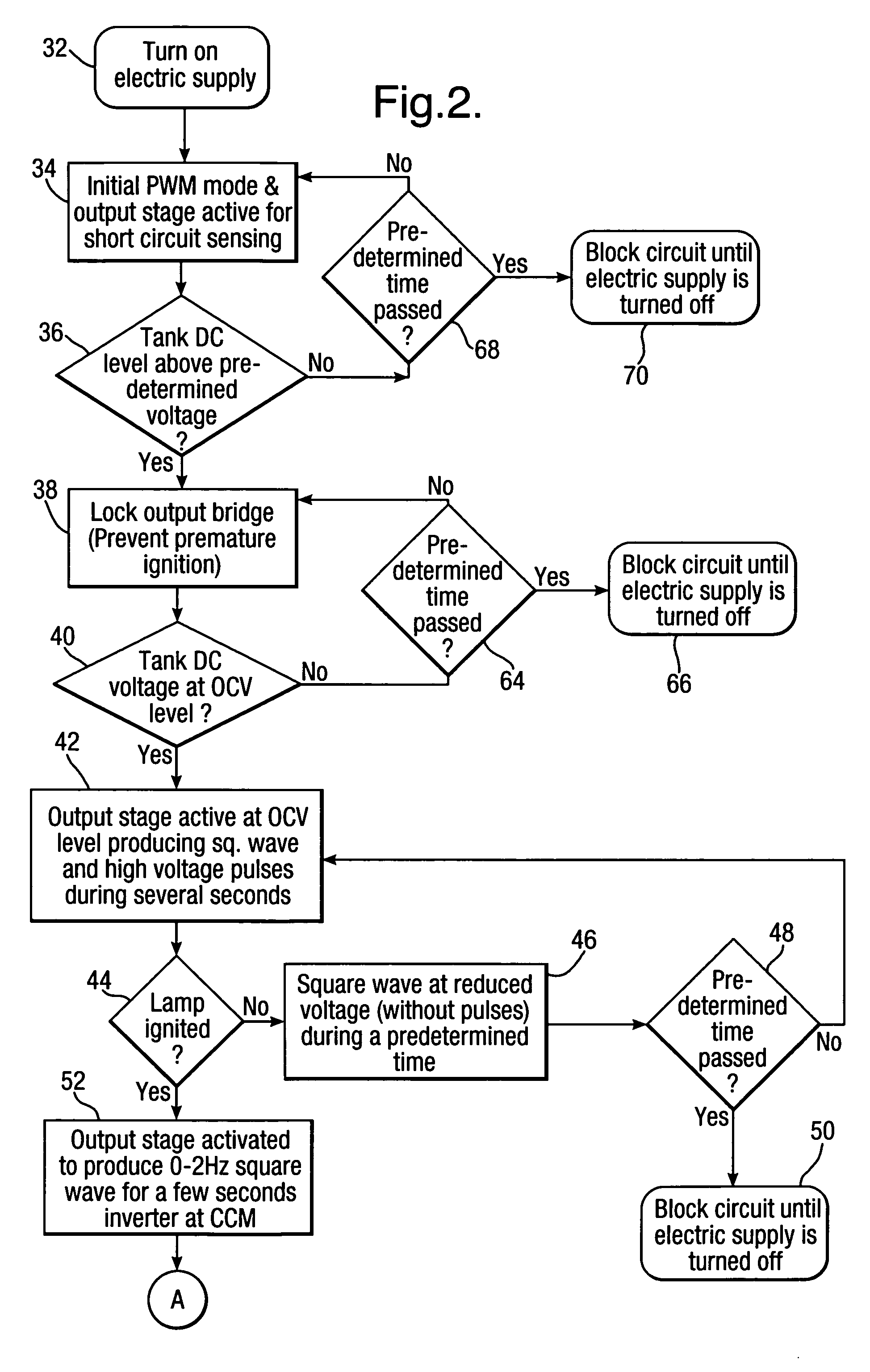
[0023]FIG. 2 illustrates a flow diagram of a preferred embodim...


PUM


Abstract

There is provided a process for operating a High Intensity Discharge (HID) lamp, having stable and transient operating phases, by a digitally controlled circuit that includes a DC supply and an inverter. During the stable operating phase of the lamp, the inverter's input DC voltage is maintained at a value depending on the lamp voltage.

Description

FIELD OF THE INVENTION[0001]The present invention relates to the operation of High Intensity Discharge (HID) lamps, and more particularly to a process for igniting, operating and monitoring the operation of HID lamps.BACKGROUND OF THE INVENTION[0002]In recent years, an increasing number of electronic ballasts are being used in the lighting industry relating to HID lamps. State of the art electronic ballasts utilize a circuit comprising a passive input filter, a Power Factor Correction (PFC) stage, an inverter and an ignitor. The state of the art ballasts are designed to maintain a relatively high Open Circuit Voltage (OCV) and high DC voltage source for the inverter. Consequently, unnecessary losses are developed in the circuit, specifically, but not exclusively, during the lamp's initial transient phase that follows the ignition of the arc while the lamp's voltage is low and its current is high.SUMMARY OF THE INVENTION[0003]It is therefore a broad object of the present invention to...

Claims


Application Information

Patent Timeline
Patent Type & Authority Patents(United States)
IPC IPC(8): H05B37/02H05B41/16H05BH05B41/288
CPCH05B41/2885Y02B20/202Y02B20/00
Inventor FISHBEIN, OMRIEREZ, ERAN
Owner ELTAM EIN HASHOFET
Why Eureka
Try Eureka