
Diamond culling of small primitives

a technology of primitives and diamonds, applied in the field of diamond culling of small primitives, can solve the problems of limiting rendering speed, large number of primitives, and inability to meet the optimal center coverage rul

Active Publication Date: 2007-12-11
NVIDIA CORP
View PDF9 Cites 66 Cited by
  • Summary
  • Abstract
  • Description
  • Claims
  • Application Information

AI Technical Summary

Benefits of technology

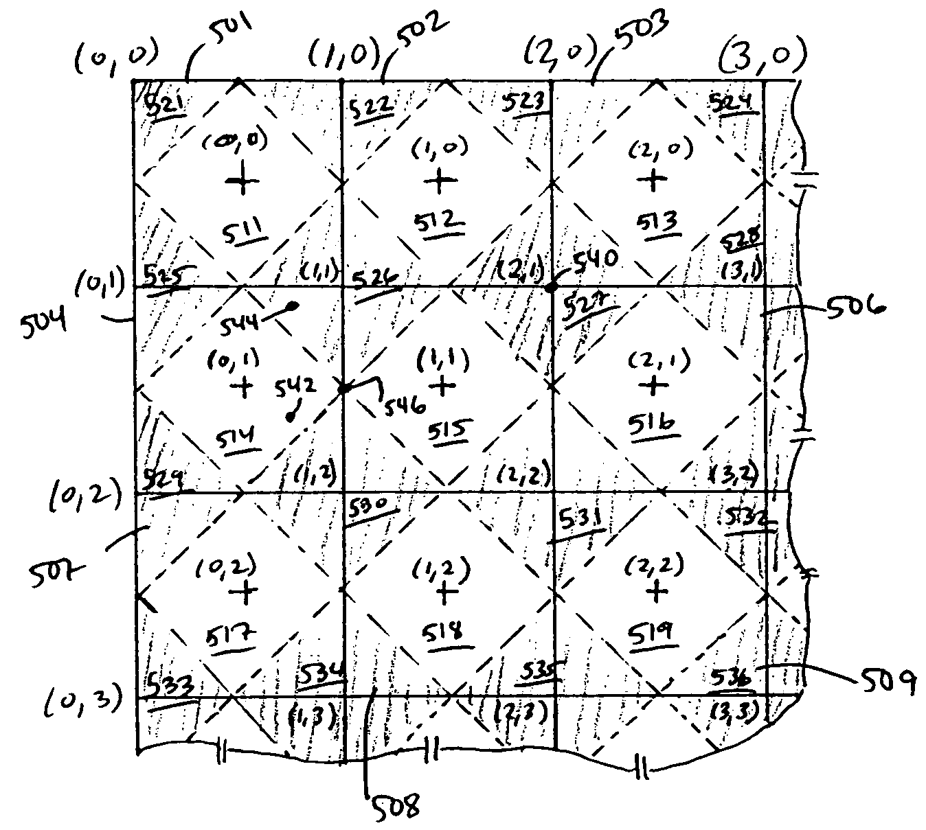
[0009]Embodiments of the present invention provide devices and methods for culling small primitives that do not cover (or hit) any pixels during pixel generation. A boundary, such as a diamond, is defined around a pixel center, with pixel coverage being determined for at least some types of primitives based on whether the boundary is crossed. The boundaries divide the raster into internal regions and external regions, and each region is assigned a unique canonical identifier. Each vertex of a primitive is assigned the canonical identifier corresponding to the region in which that vertex is located. One or more culling rules based on the canonical coordinates of the vertices is then applied to cull primitives that do not satisfy the boundary crossing rules. Small lines and polygons can be culled based on the canonical location identifiers of their vertices. Such culling may occur at any point after screen locations of the vertices have been determined.

Problems solved by technology

One challenge in determining coverage is the case where a primitive covers only part of a pixel.
For rasterizing lines, a center coverage rule is usually not optimal, and other rules are often used instead.
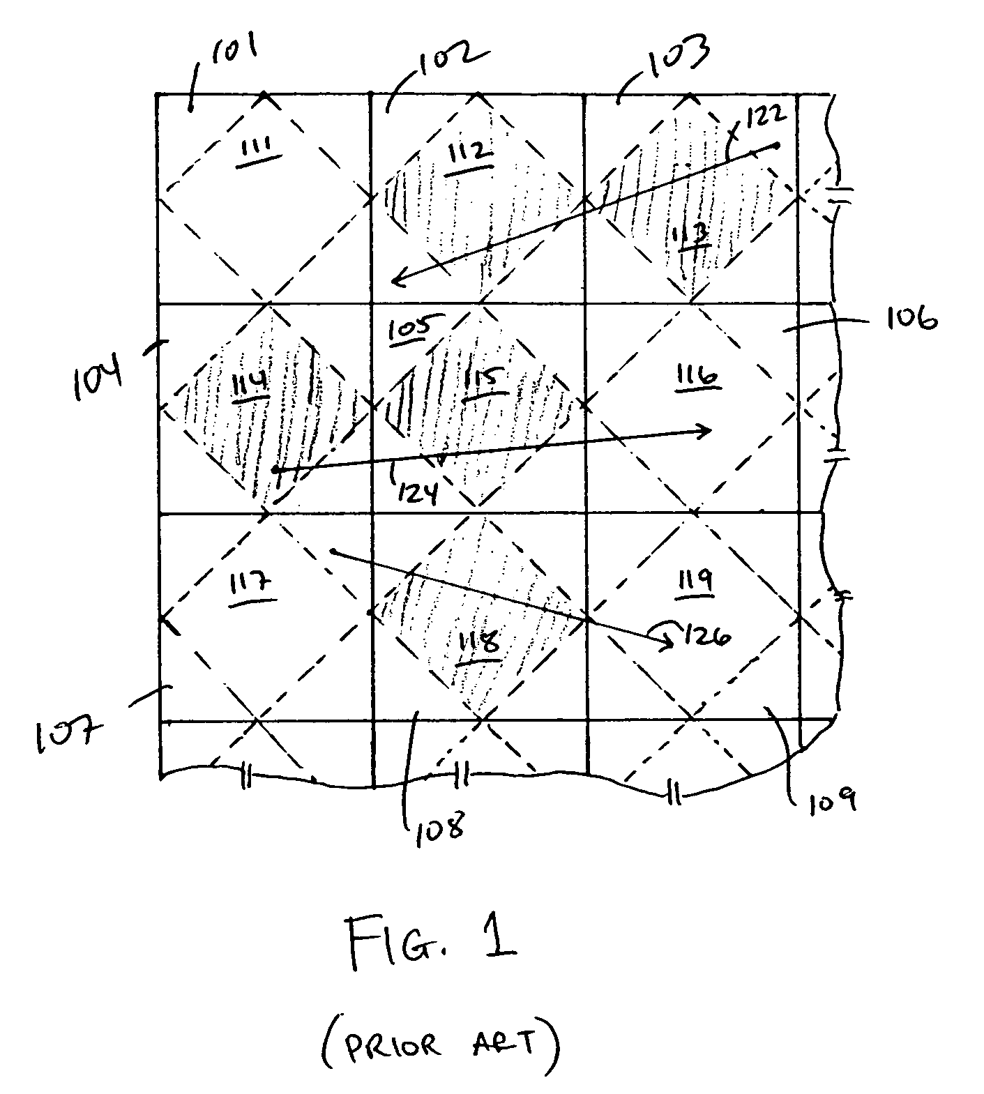
Complex images, such as those typically found in 3D video games or other applications, involve a very large number of primitives, and one of the factors that limits rendering speed is the time needed for the rasterizer to process all of the primitives.
Existing culling techniques generally do not systematically identify or cull such primitives, due in part to a lack of computationally efficient ways to identify and cull all such primitives without also culling some primitives that should be drawn.
Thus, the rasterizer may process a significant number of primitives that do not actually cover any pixels, which results in slower rendering.

Method used


Image

  • Diamond culling of small primitives
  • Diamond culling of small primitives
  • Diamond culling of small primitives

Examples


Embodiment Construction

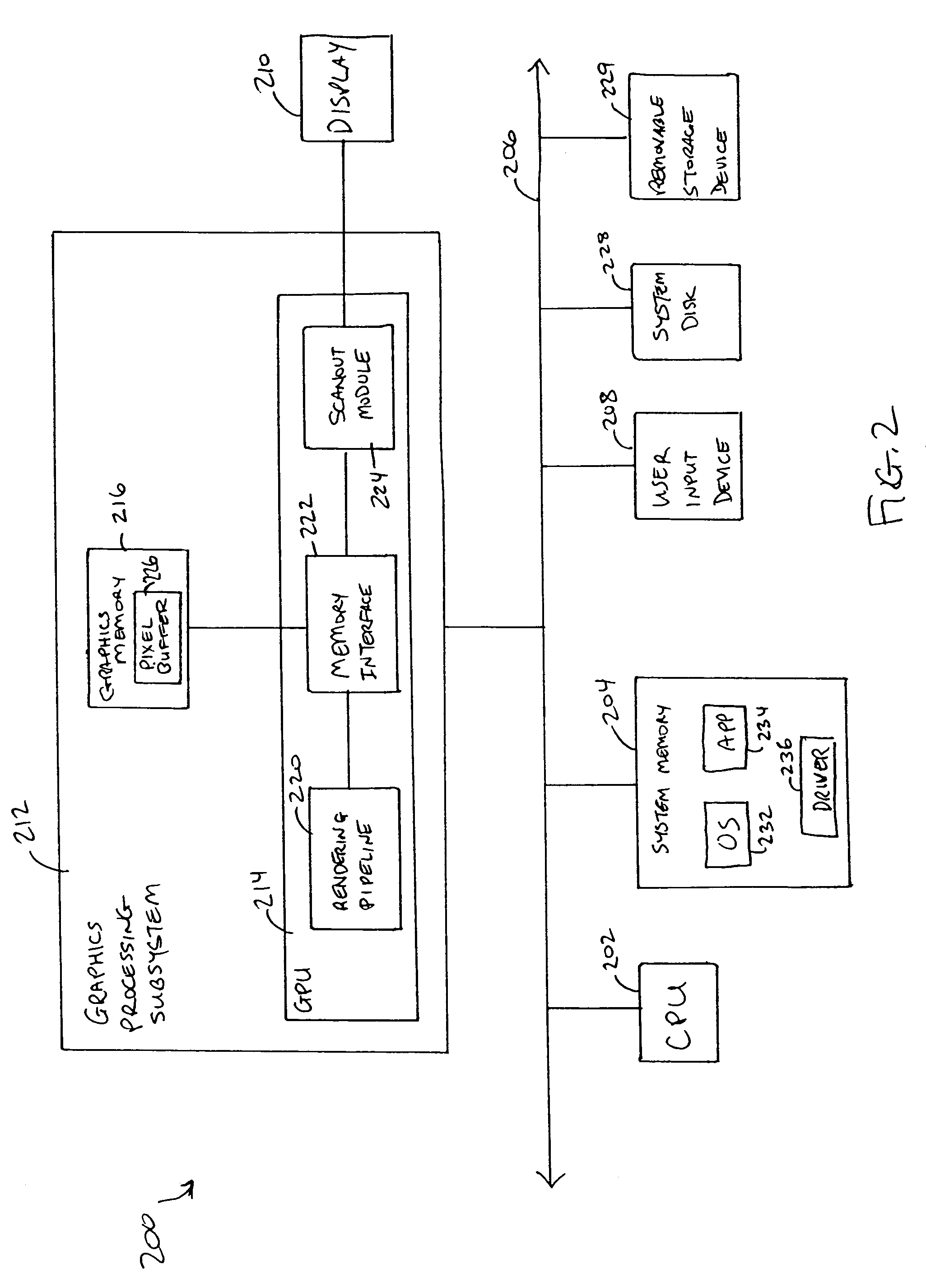
[0025]Embodiments of the present invention provide devices and methods for culling small primitives that do not cover (or hit) any pixels during pixel generation, based on boundaries defined around pixel centers that divide the pixel raster into internal regions and external regions, with each region being assigned a unique canonical identifier. Each vertex of a primitive is assigned the canonical identifier corresponding to the region in which that vertex is located, and culling rules are defined with reference to the canonical coordinates of the vertices. Small lines and polygons can be culled based on the canonical location identifiers of their vertices. Such culling may occur at any point after screen locations of the vertices have been determined. Culling is advantageously implemented in a graphics rendering pipeline, which may be integrated into a graphics processor of a computer system.

[0026]FIG. 2 is a block diagram of a computer system 200 according to an embodiment of the ...


PUM


Abstract

Graphics processing devices and methods are provided for culling small primitives that do not cover any pixels. A boundary (e.g., a diamond) is defined around a pixel center, with pixel coverage being determined for some types of primitives based on whether the boundary is crossed. The boundaries divide the raster into internal regions and external regions. Each region is assigned a unique canonical identifier. Each vertex of a primitive is assigned the canonical identifier corresponding to the region that contains that vertex. The canonical coordinates of the vertices are used to cull primitives that do not satisfy the boundary crossing coverage rules for any pixels.

Description

CROSS-REFERENCES TO RELATED APPLICATIONS[0001]The present disclosure is related to commonly-assigned co-pending U.S. patent application Ser. No. 10 / 913,667, filed on the same date as the present application, entitled “Culling Before Setup,” which disclosure is incorporated herein by reference for all purposes.BACKGROUND OF THE INVENTION[0002]The present invention relates in general to computer rendering technologies, and in particular to techniques for diamond culling of small primitives.[0003]Computer-based rendering systems generally receive image data in the form of primitives (such as lines or triangles) that represent objects to be drawn. After transforming the primitives to a viewing space, the primitives are rasterized to generate pixel data values. Rasterization generally involves determining, for each pixel, which primitive should be seen on the screen and shading the pixel based on attributes of that primitive. As one aspect of this process, it is generally necessary to de...

Claims


Application Information

Patent Timeline
Patent Type & Authority Patents(United States)
IPC IPC(8): G06T15/40
CPCG06T15/40
Inventor GOODMAN, CHRISTOPHER J.WITTENBRINK, CRAIG M.HASSLEN, ROBERT J.OGLETREE, THOMAS M.WHITMAN, SCOTT R.
Owner NVIDIA CORP
Learn More