Vehicle steering apparatus

a steering apparatus and vehicle technology, applied in the direction of steering linkages, electrical steering, transportation and packaging, etc., can solve the problems of difficult to provide the required ackerman steer angle (=l/r), unsatisfactory limitation of a and difficult to remarkably enhance or improve the link efficiency. , to achieve the effect of enhancing the steering link efficiency and reducing the minimum turning radius of the vehicl

Inactive Publication Date: 2007-12-18
NISSAN MOTOR CO LTD
View PDF20 Cites 83 Cited by
  • Summary
  • Abstract
  • Description
  • Claims
  • Application Information

AI Technical Summary

Benefits of technology

[0007]Furthermore, in the steering apparatus of JP2002-225733, the cable back-up mechanism is permanently linked via the column shaft to the steering wheel irrespective of whether the clutch is engaged or disengaged, inner cables of the cable back-up mechanism are wound up or off continuously in synchronism with rotation of the steering wheel, irrespective of whether the steering system is operated in the SBW operating mode or in the back-up operating mode. Owing to the continuous winding-up and winding-off operations, there is an increased tendency for the inner cable and the outer tube in sliding-contact with each other, to undesirably wear rapidly. This deteriorates the durability of the back-up mechanism. During the continuous winding-up and winding-off operations in synchronism with rotation of the steering wheel, friction between the inner cable and the outer tube means friction resistance to any movement of the steering wheel, in other words, increased steering effort, thus deteriorating a steering feel.
[0009]Accordingly, it is a main object of the invention to provide a vehicle steering apparatus capable of giving a differential rack stroke between left and right rack shaft portions during steering operation, and thus further reducing a minimum radius of turn of the vehicle, for the substantially same steering system layout as the conventional steering apparatus.
[0010]It is another object of the invention to provide a vehicle steering apparatus capable of balancing two contradictory requirements, that is, enhanced steering link efficiency and required Ackerman steer angle (required Ackerman ratio).
[0011]It is another object of the invention to provide an SBW vehicle steering apparatus with a back-up mechanism, capable of compensating for and eliminating a deviation (or a lack) of the actual steer angle at steered wheels from the desired steer angle during a back-up operating mode, even in presence of undesirable slippage of a clutch used to couple steering input and output sections to each other via a back-up system, for instance due to excessive torque transmission above a power-transmission limit.
[0012]It is another object of the invention to provide an SBW vehicle steering apparatus with a back-up mechanism, capable of shifting from an SBW operating mode to a back-up operating mode, while ensuring a condition where there is a less discrepancy between a neutral position of a steering wheel and a neutral position corresponding to zero average steer angle of a pair of steered wheels, even in presence of a system failure of a single SBW control system.

Problems solved by technology

This undesirably limits a minimum turning radius of the vehicle.
However, it is difficult to remarkably enhance or improve the link efficiency determined by the relative linkage installation-position relationship based on the Ackerman steer angle δ (=L / R) by way of only the suspension geometry, because of the layout limits.
In contrast, assuming that the proper installation-position relationship between the tie rods and steering knuckle arms is determined to provide a higher link efficiency, it is difficult to provide the required Ackerman steer angle δ (=L / R).
During the back-up operating mode with the clutch engaged, in the presence of excessive steering torque transmission from the steering wheel via the cable back-up mechanism and the rack-and-pinion steering gear device to the steered road wheels, the clutch tends to slip owing to the excessive torque.
This results in a lack of the actual steer angle at the steered road wheels, that is, a minus deviation of the actual steer angle from the desired steer angle.

Method used


Image

  • Vehicle steering apparatus
  • Vehicle steering apparatus
  • Vehicle steering apparatus

Examples


Embodiment Construction

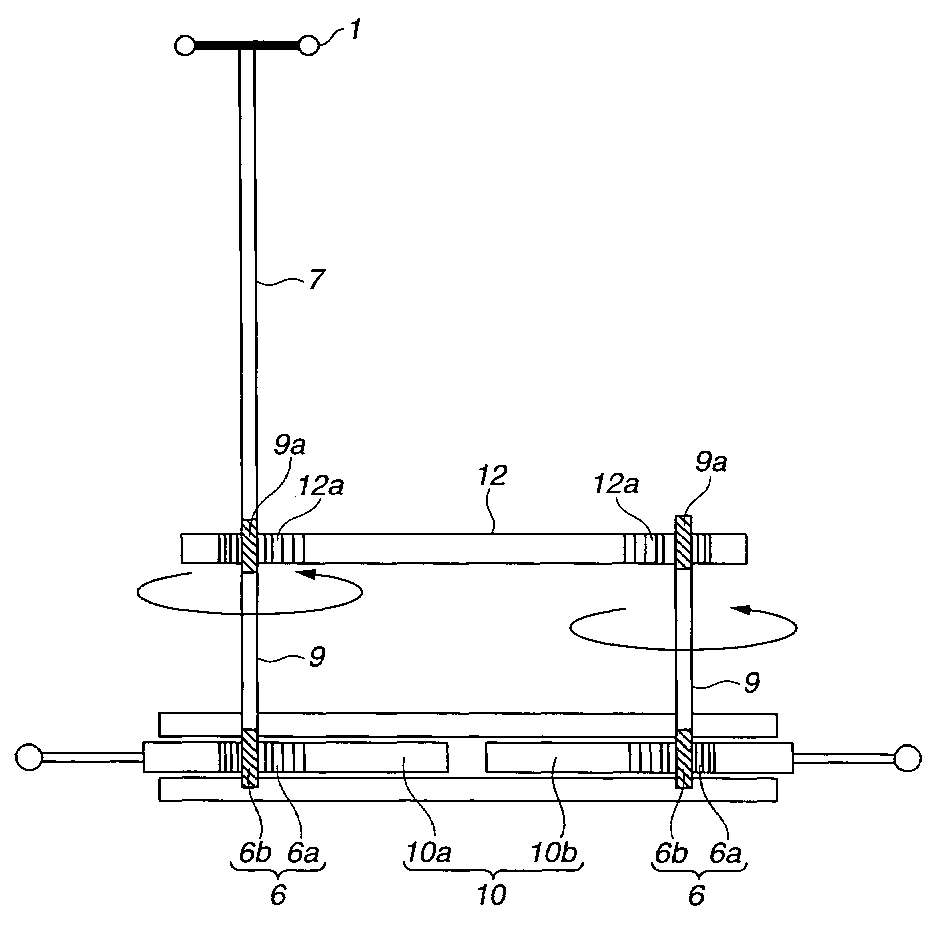
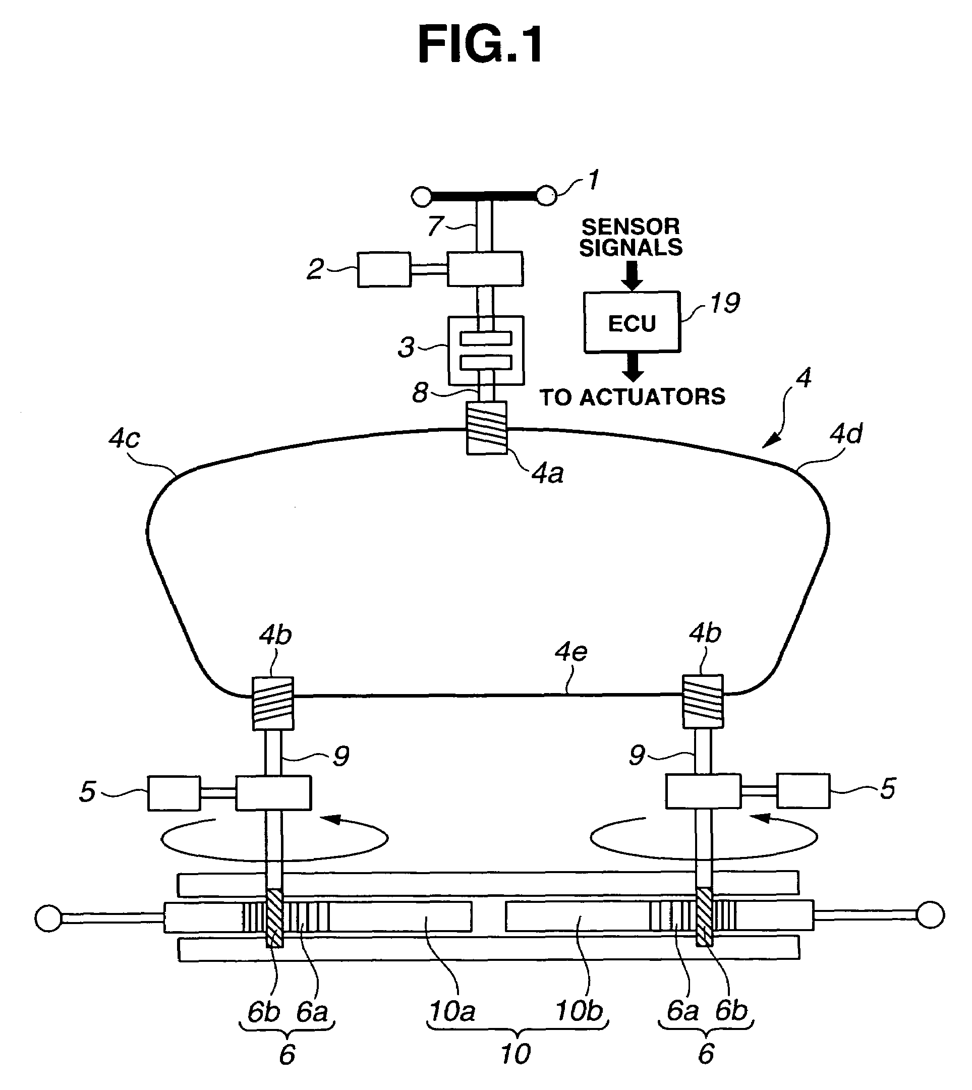
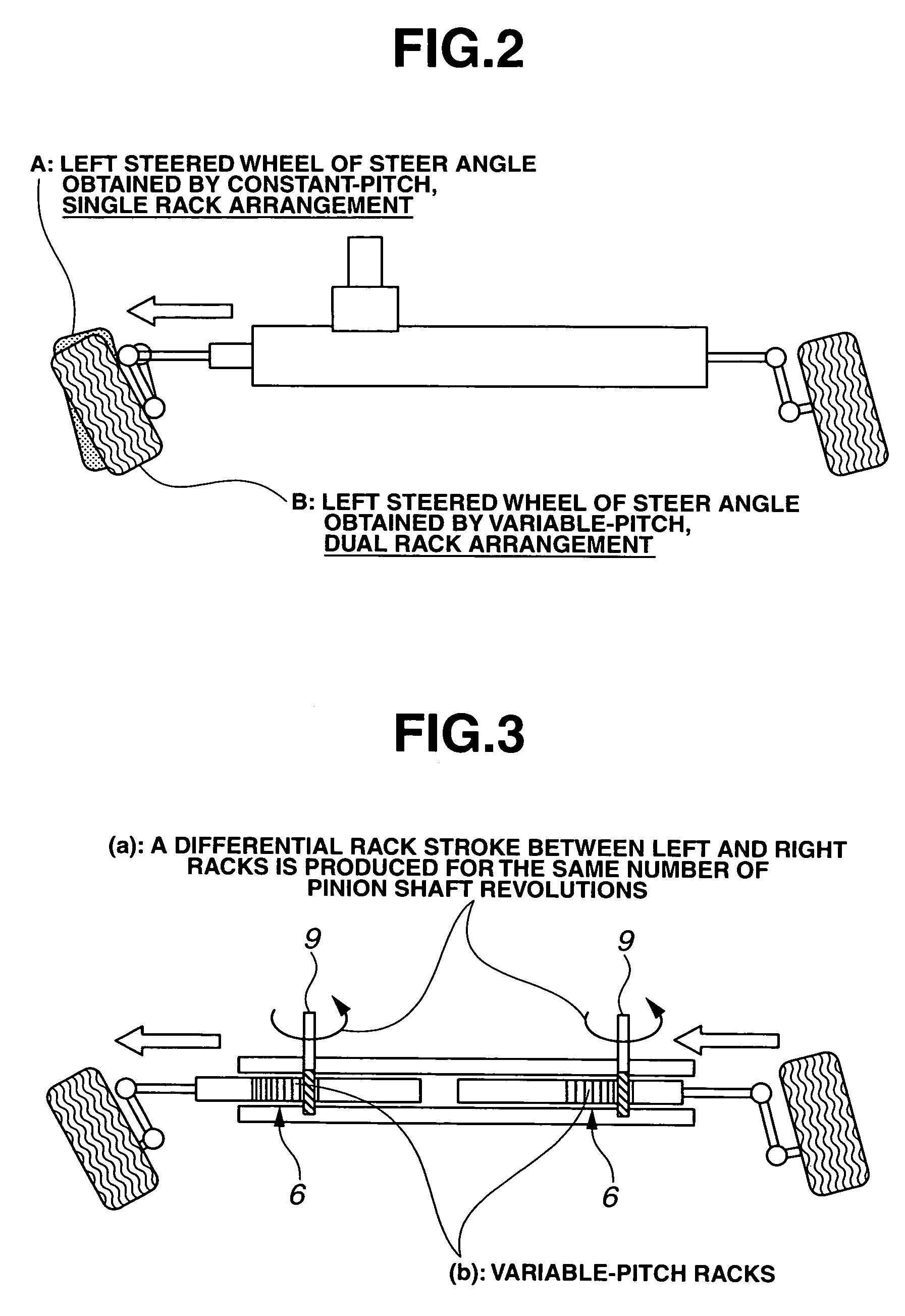
[0057]Referring now to the drawings, particularly to FIG. 1, the vehicle steering apparatus of the embodiment is exemplified in an steer-by-wire (SBW) vehicle steering apparatus equipped with a reaction torque actuator (a reaction force actuator or a feedback actuator) 2, a clutch device 3, a cable back-up mechanism 4 having three pulleys 4a, 4b, and 4b, and two steering actuators 5, 5. Note that the vehicle steering apparatus of the embodiment has a two-split variable-pitch rack-and-pinion arrangement, simply a variable-pitch dual rack arrangement (described later), comprised of left and right variable-pitch racks (variable racks) 6, 6, being movable independently of each other and serving as a steer angle conversion mechanism (simply, a steer angle converter) that enables a differential rack stroke between left and right rack strokes. As seen in FIG. 1, a first column shaft 7 is connected to a steering wheel 1, serving as part of a steering input section.

[0058]Feedback actuator 2 ...


PUM


Abstract

A vehicle steering apparatus includes a steering input section having at least a steering wheel to which steering input is applied, and a steering output section having at least a steering rack shaft and operatively associated with left and right steered wheels for steering the steered wheels by steering-rack-shaft movement produced by a steering force determined based on the steering input and transmitted directly or indirectly to the steering rack shaft. The steering rack shaft is split into left and right movable rack shaft portions. Also provided is a steer angle converter enabling a differential rack stroke between left and right rack strokes of the left and right movable rack shaft portions. The steer angle converter is constructed by at least one of a variable-pitch dual rack arrangement and a dual taper-pulley arrangement of a cable back-up mechanism.

Description

TECHNICAL FIELD[0001]The present invention relates to a vehicle steering apparatus through which steered wheels are turned by movement of a rack shaft of a rack-and-pinion steering gear device in presence of steering input to a steering wheel, and more specifically to a steer-by-wire (SBW) vehicle steering apparatus with a back-up system disposed between an operating section or a steering input section (containing a steering wheel) and a steering output section (containing a rack-and-pinion steering gear device) linked to steered wheels, and an SBW controller capable of executing (i) an SBW operating mode for SBW control for both of the steering input and output sections mechanically separated from each other and (ii) a back-up operating mode during which the steering input and output sections are mechanically coupled to each other via the back-up system, in presence of an SBW system failure.BACKGROUND ART[0002]In recent years, there have been proposed and developed various automoti...

Claims


Application Information

Patent Timeline
Patent Type & Authority Patents(United States)
IPC IPC(8): B62D5/04B62D1/16B62D5/00B62D6/00B62D7/12
CPCB62D1/163B62D7/09B62D5/008B62D5/003B62D5/001
Inventor HARA, KAZUOKUBOKAWA, NORIKIOSONOI, TETSUYAEGUCHI, TAKAAKISHITAMITSU, KIYOTAKAONO, HITOSHI
Owner NISSAN MOTOR CO LTD
Why Eureka
Try Eureka