Deep pocket seat assembly in modular fuel injector with fuel filter mounted to spring bias adjusting tube and methods

a fuel injector and modular technology, applied in the direction of valve operating means/release devices, machines/engines, mechanical equipment, etc., can solve the problem that only the injection sample of known injectors can be tested

Active Publication Date: 2007-12-18
VITESCO TECH USA LLC
View PDF11 Cites 14 Cited by
  • Summary
  • Abstract
  • Description
  • Claims
  • Application Information

AI Technical Summary

Problems solved by technology

It is also believed that examples of known injectors can only be tested after final assembly has been completed.

Method used


Image

  • Deep pocket seat assembly in modular fuel injector with fuel filter mounted to spring bias adjusting tube and methods
  • Deep pocket seat assembly in modular fuel injector with fuel filter mounted to spring bias adjusting tube and methods
  • Deep pocket seat assembly in modular fuel injector with fuel filter mounted to spring bias adjusting tube and methods

Examples


Embodiment Construction

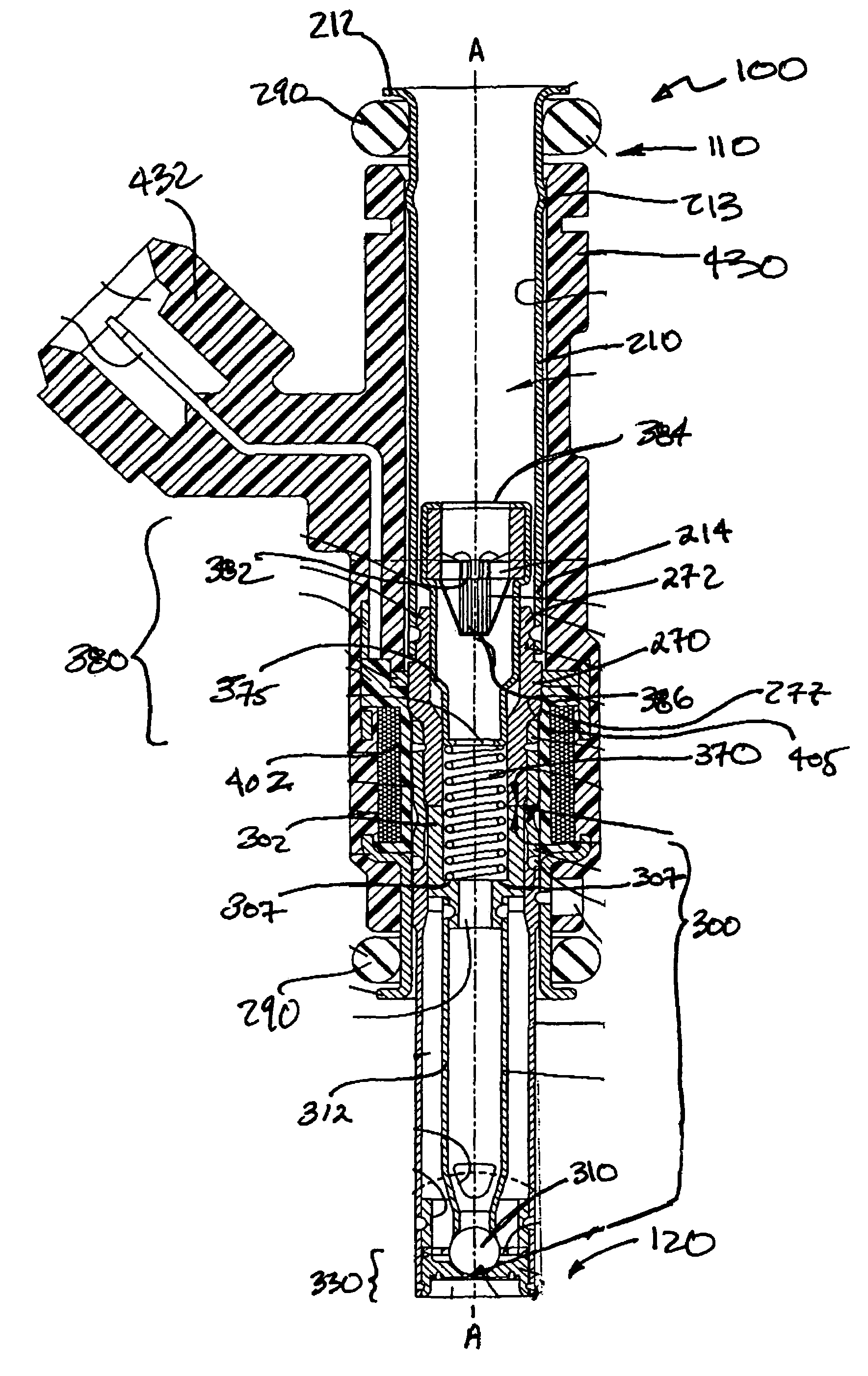
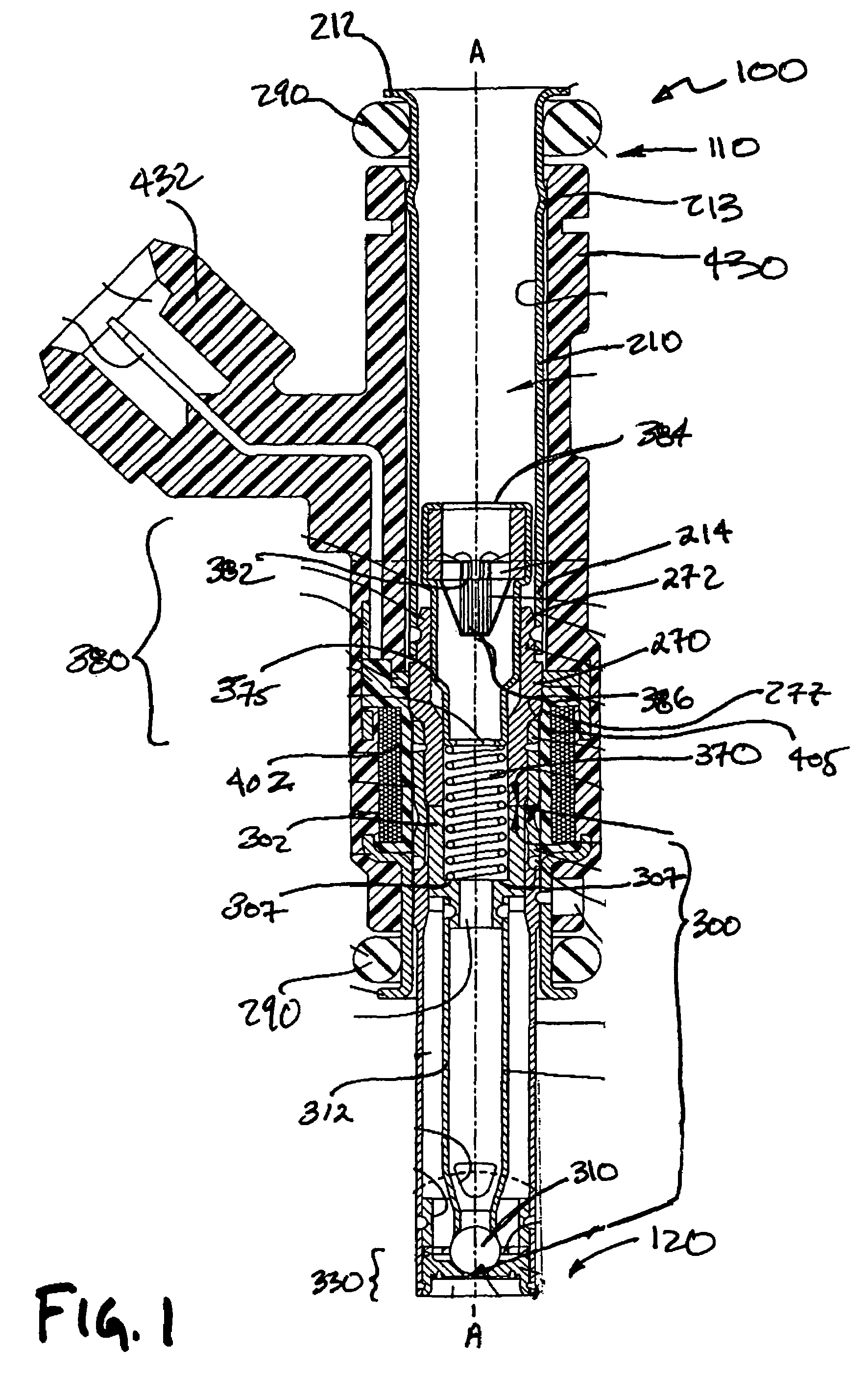
[0028]Shown in FIGS. 1 and 1A are preferred embodiments of a solenoid actuated fuel injector 100 for dispensing a quantity of fuel that is to be combusted in an internal combustion engine (not shown). The fuel injector 100 extends along a longitudinal axis A--A between a first injector end 110 and a second injector end 120, and includes a valve group subassembly 200, shown in FIG. 2, and a power group subassembly 400, shown in FIG. 5. The valve group subassembly 200 performs fluid handling functions, e.g., defining a fuel flow path and prohibiting fuel flow through the injector 100. The power group subassembly 400 performs electrical functions, e.g., converting electrical signals to a driving force for permitting fuel flow through the injector 100.

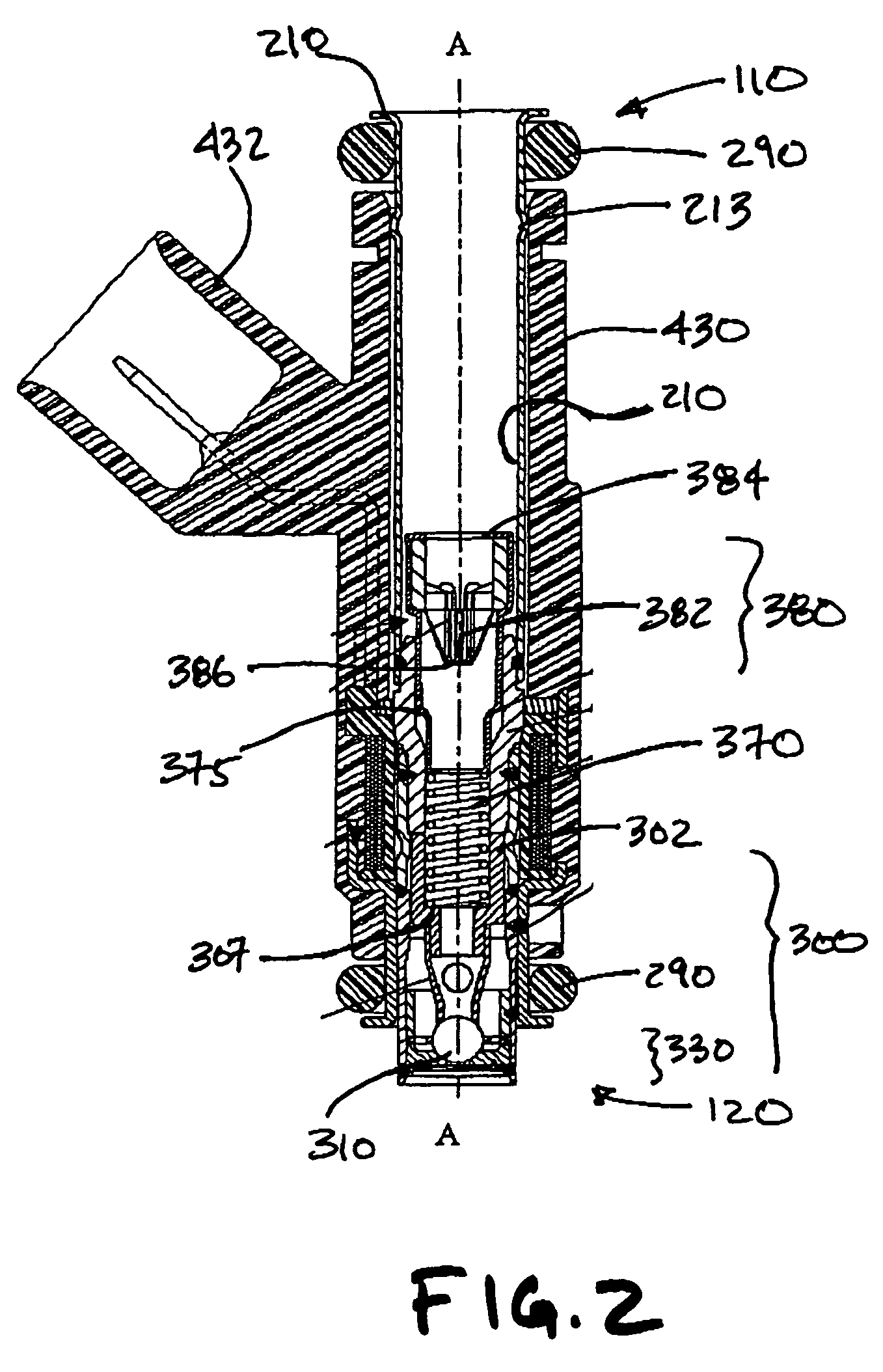
[0029]Referring to FIGS. 1 and 1A and shown specifically in FIG. 2 are various preferred embodiments of the valve group subassembly 200, which includes at least a tube assembly 202 extending along the longitudinal axis A-A between a first ...


PUM


Abstract

A fuel injector and various methods relating to the assembly of the fuel injector. The fuel injector includes a power group subassembly and a valve group subassembly having a respectively connected first and second connector portions. The power group subassembly includes an electromagnetic coil, a housing, at least one terminal, and at least one overmold formed over the coil and housing. The valve group subassembly insertable within the overmold includes a tube assembly having an inlet tube and a filter assembly. A pole piece couples the inlet tube to one end of a non-magnetic shell having a valve body coupled to the opposite end. An axially displaceable armature assembly confronts the pole piece and is adjustably biased by a member engaged with an adjusting tube with a filter assembly mounted thereon. The seat assembly includes a flow portion and a securement portion having respective first and second axial lengths at least equal to one another.

Description

BACKGROUND OF THE INVENTION[0001]It is believed that examples of known fuel injection systems use an injector to dispense a quantity of fuel that is to be combusted in an internal combustion engine. It is also believed that the quantity of fuel that is dispensed is varied in accordance with a number of engine parameters such as engine speed, engine load, engine emissions, etc.[0002]It is believed that examples of known electronic fuel injection systems monitor at least one of the engine parameters and electrically operate the injector to dispense the fuel. It is believed that examples of known injectors use electromagnetic coils, piezoelectric elements, or magnetostrictive materials to actuate a valve.[0003]It is believed that examples of known valves for injectors include a closure member that is movable with respect to a seat. Fuel flow through the injector is believed to be prohibited when the closure member sealingly contacts the seat, and fuel flow through the injector is belie...

Claims


Application Information

Patent Timeline
Patent Type & Authority Patents(United States)
IPC IPC(8): B05B1/30
CPCF02M51/005F02M51/0682F02M61/168F02M61/18F02M61/1853F02M61/188F02M61/205F02M2200/08F02M2200/505F02M2200/9069Y10S239/90F02M61/165
Inventor DALLMEYER, MICHAEL
Owner VITESCO TECH USA LLC
Why Eureka
Try Eureka