Fuel supply device

a fuel supply device and fuel filter technology, applied in the direction of liquid fuel feeders, fuel injecting pumps, machines/engines, etc., can solve the problems of inability to increase inhibit the flow rate, and block the fuel filter, so as to reduce the space for installing the fuel filter. , the effect of increasing the size of the fuel filter

Active Publication Date: 2008-03-18
DENSO CORP
View PDF18 Cites 32 Cited by
  • Summary
  • Abstract
  • Description
  • Claims
  • Application Information

AI Technical Summary

Benefits of technology

[0009]It is therefore an object of the present invention to locate a fuel filter downstream of a feed pump and to reduce the size of the fuel filter.
[0011]Since the fuel filter is located downstream of the feed pump, a positive pressure of the feed pump is applied to the fuel filter. Accordingly, a passing pressure of the fuel filter increases compared to the case where the fuel filter is located upstream of the feed pump. Thus, even in the case where viscosity of the fuel increases and the fuel becomes wax-like at low temperature, clogging of the fuel filter or an insufficient flow rate can be inhibited. Since the flow rate restricting device is located upstream of the suction quantity control valve, a flow rate of the fuel passing through the fuel filter can be restricted. Therefore, an increase in the size of the fuel filter is inhibited even if the fuel filter is located downstream of the feed pump. As a result, a space for installing the fuel filter can be reduced.

Problems solved by technology

Thus, even in the case where viscosity of the fuel increases and the fuel becomes wax-like at low temperature, clogging of the fuel filter or an insufficient flow rate can be inhibited.
Therefore, an increase in the size of the fuel filter is inhibited even if the fuel filter is located downstream of the feed pump.

Method used


Image

  • Fuel supply device
  • Fuel supply device
  • Fuel supply device

Examples


second embodiment

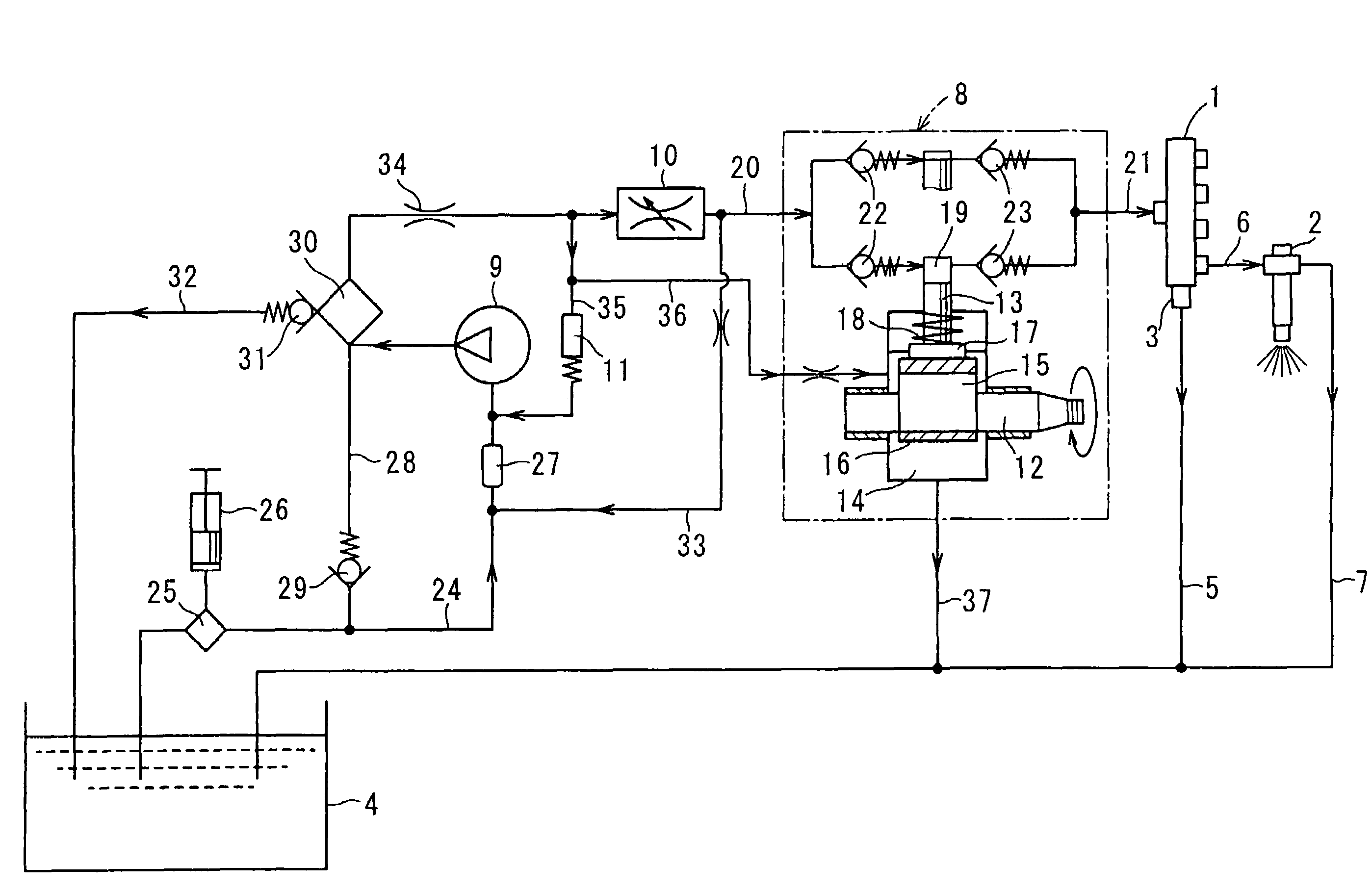
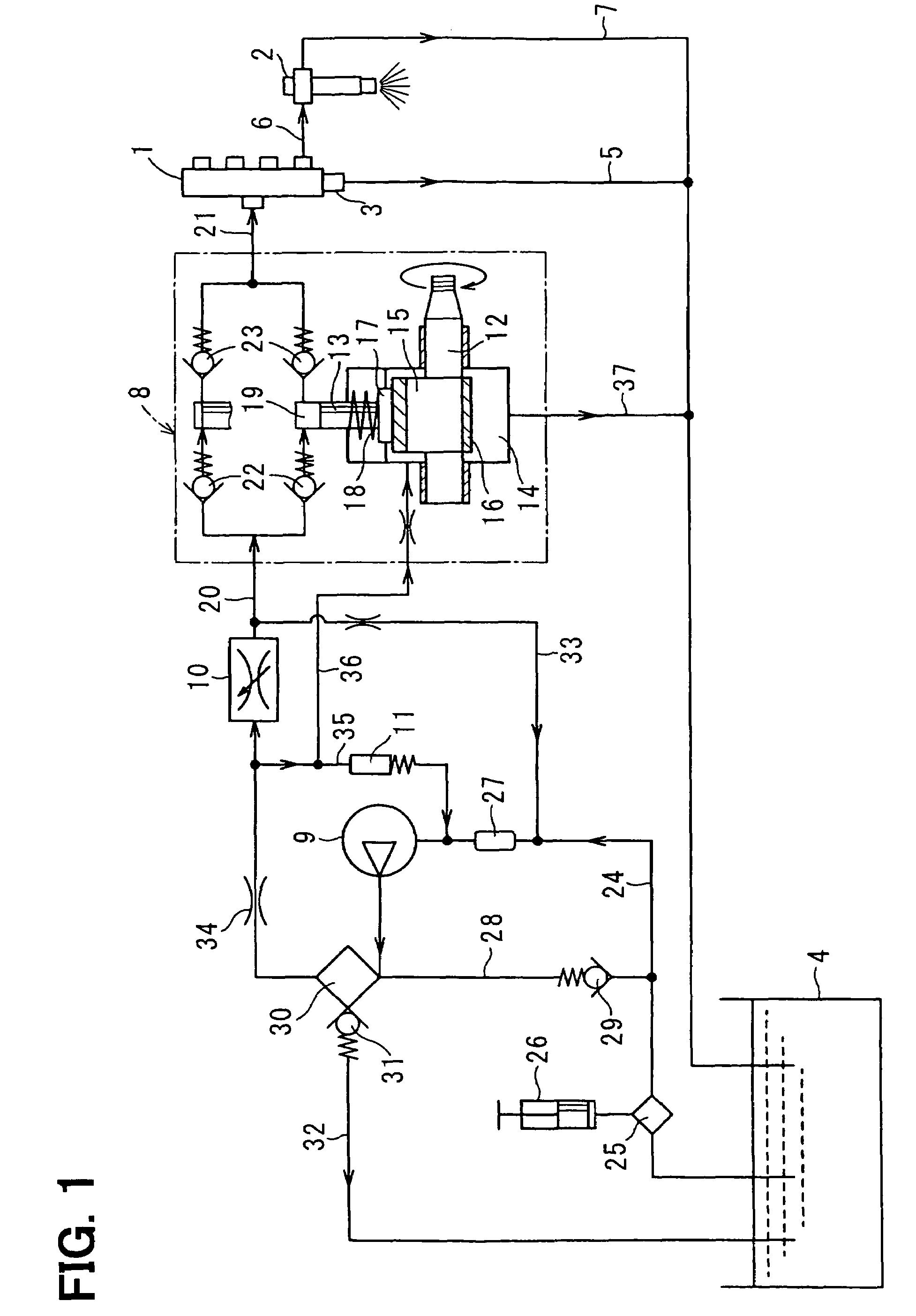
[0043]Referring to FIG. 2, a pressure accumulation fuel injection system according to the present invention is illustrated. The fuel injection system shown in FIG. 2 has an air-bleeding valve 38 in addition to the relief valve 31.

[0044]The relief valve 31 opens if the fuel pressure acting on the fuel filter 30 exceeds the pressure-resistance upper limit value of the fuel filter 30.

[0045]The air-bleeding valve 38 is located in an air-bleeding passage 39 connected with a portion of the fuel pipe system where the air tends to collect. The air-bleeding valve 38 receives the discharge pressure of the feed pump 9 and opens. The air-bleeding passage 39 communicates with the fuel tank 4 through the fuel pipe 32, for example. Thus, regardless of the operation of the relief valve 31, the air-bleeding can be performed in accordance with the operation of the feed pump 9.

third embodiment

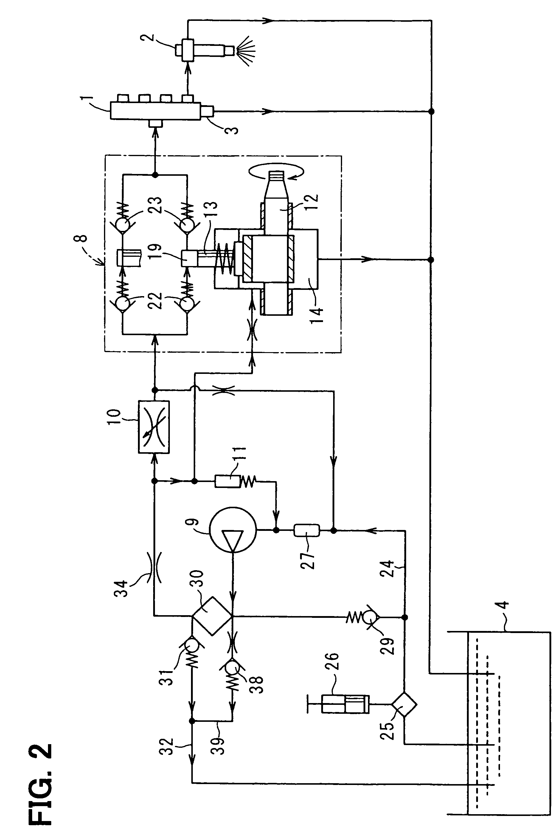
[0046]Referring to FIG. 3, a pressure accumulation fuel injection system according to the present invention is illustrated. In the fuel injection system of this embodiment, an orifice 34 as a flow rate restricting device is located upstream of (on suction side of) the feed pump 9 as shown in FIG. 3. The orifice 34 is located between the feed pump 9 and the gauze filter 27 upstream of the feed pump 9 as shown in FIG. 3.

[0047]Thus, the orifice 34 restricts the suction quantity of the feed pump 9, and a time number the relief valve 31 operates is reduced. Accordingly, a fuel pressure seldom exceeds the pressure-resistance upper limit value of the fuel filter 30, and the time number the relief valve 31 opens decreases. Thus, durability of the relief valve 31 is improved.

fourth embodiment

[0048]Referring to FIG. 4, a pressure accumulation fuel injection system according to the present invention is illustrated. In the fuel injection system of this embodiment, an electromagnetic valve 40 functions as a flow rate restricting device. An ECU 41 controls the electromagnetic valve 40 based on information about rotation speed (RPM) of the diesel engine, the injection quantity (Q) of the injector 2 and the fuel pressure (P) of the common rail 1, for example. Thus, the flow rate of the fuel passing through the fuel filter 30 can be controlled finely in accordance with the operating state of the engine.

[0049]Referring to FIG. 5, a fuel filter 30 and a relief valve 31 according to a fifth embodiment of the present invention is illustrated. The relief valve 31 of this embodiment has a function of bleeding the air from the fuel pipe system in the fuel injection system of the first or third embodiment, which does not include the air-bleeding valve 38 used in the system of the secon...


PUM


Abstract

A fuel filter is located downstream of a feed pump to filter fuel discharged from the feed pump. An orifice is located between the fuel filter and a suction quantity control valve to restrict a flow rate of the fuel passing through the fuel filter. A positive pressure of the feed pump is applied to the fuel filter, and a passing pressure at the fuel filter increases. Even if viscosity of the fuel increases and the fuel becomes wax-like at low temperature, clogging of the fuel filter or an insufficient flow rate can be inhibited. The orifice restricts the flow rate of the fuel passing through the fuel filter. Accordingly, an increase in size of the fuel filter can be prevented even if the fuel filter is located downstream of the feed pump.

Description

CROSS REFERENCE TO RELATED APPLICATION[0001]This application is based on and incorporates herein by reference Japanese Patent Application No. 2005-21770 filed on Jan. 28, 2005.BACKGROUND OF THE INVENTION[0002]1. Field of the Invention[0003]The present invention relates to a fuel supply device used in a pressure accumulation fuel injection system of an internal combustion engine. Specifically, the present invention relates to a fuel filter that filters fuel drawn by a feed pump.[0004]2. Description of Related Art[0005]A pressure accumulation fuel injection system is known as a fuel injection system of a diesel engine and the like. As shown in FIG. 7, this system has a common rail 100, a fuel supply pump 110, an injector 120 and the like. The common rail 100 accumulates high-pressure fuel. The fuel supply pump 110 pressure-feeds the fuel to the common rail 100. The injector 120 injects the high-pressure fuel supplied from the common rail 100 into a cylinder of the diesel engine.[0006]...

Claims


Application Information

Patent Timeline
Patent Type & Authority Patents(United States)
IPC IPC(8): F02M33/02F02M63/00F02M37/34F02M37/40F02M37/54
CPCF02M37/22F02M59/34F02M63/0225F02M37/0047F02M2037/226F02M37/46F02M37/34F02M37/40F02M37/54
Inventor MORI, KATSUMIKURODA, AKIHIRO
Owner DENSO CORP
Why Eureka
Try Eureka