Fuel filter device

a filter device and fuel technology, applied in the direction of filtration separation, machines/engines, separation processes, etc., can solve the problems of difficult to reduce the fiber diameter difficult to prevent the clogging of the non-woven layer formed with the melt blown method for a long time, and the non-woven layer formed with the span bond method does not function as a pre-filter effectively, etc., to achieve the effect of improving the filtering accuracy of the filter device, easy welding

Inactive Publication Date: 2005-02-03
NIFCO INC
View PDF12 Cites 31 Cited by
  • Summary
  • Abstract
  • Description
  • Claims
  • Application Information

AI Technical Summary

Benefits of technology

[0022] With such a structure, after constituent members formed in a sheet or a mat shape are laminated, each layer is easily integrated with welding to form the bag-shaped filter member.
[0023] Accordi...

Problems solved by technology

Specifically, it is difficult to reduce a fiber diameter of the non-woven layer formed with the span bond method, so that the average diameter of the air holes of the non-woven layer has a limit (20 μm at the minimum) to make the mesh finer.
(In other words, a filtering slope becomes steep, so that the non-woven layer formed with the span bond method does not function as a pre-filter effectively.)
Consequently, in the filter ...

Method used


Image

  • Fuel filter device
  • Fuel filter device
  • Fuel filter device

Examples


Embodiment Construction

[0027] Hereinafter, embodiments of the present invention will be described with reference to FIGS. 1 to 3.

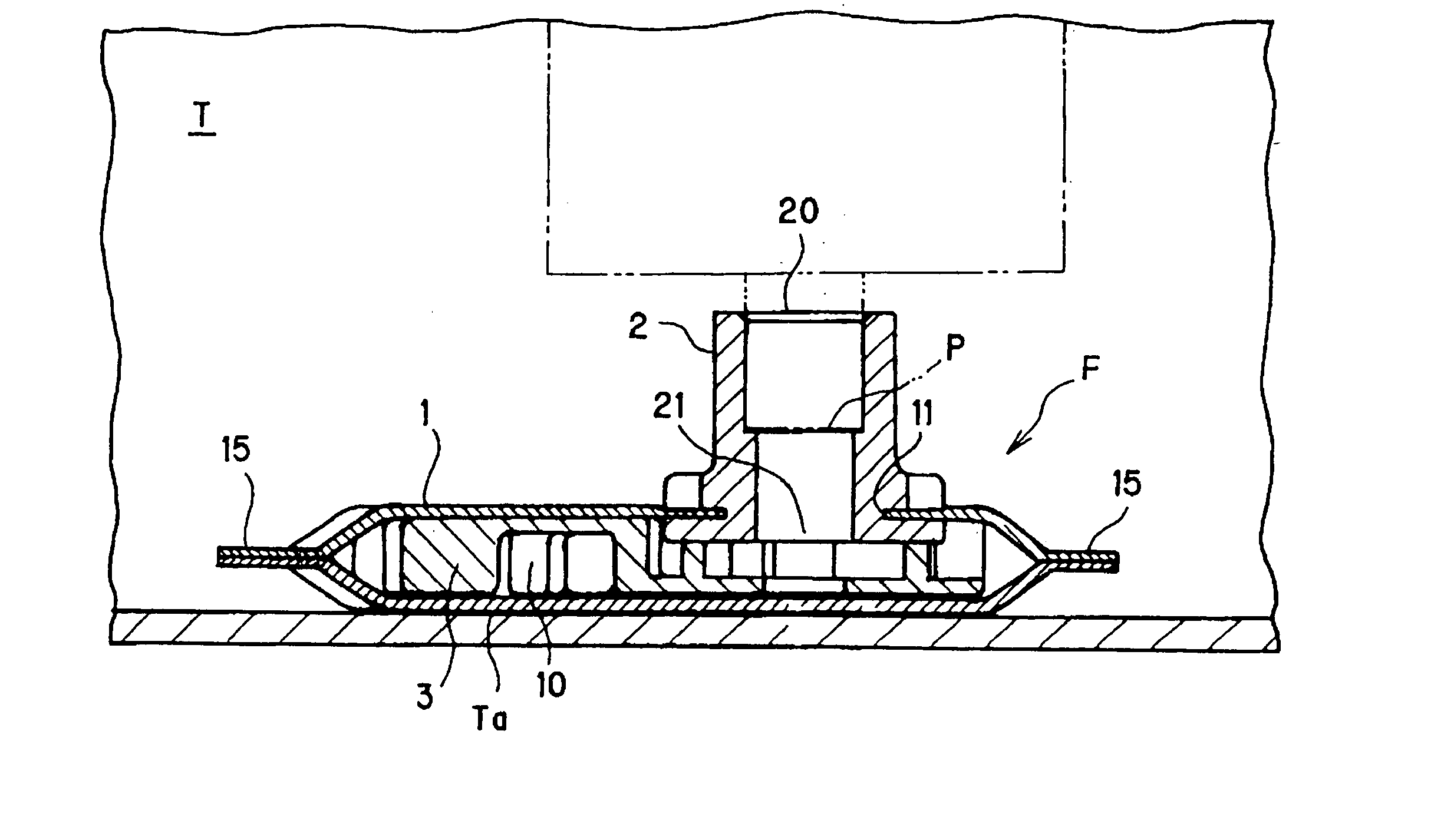
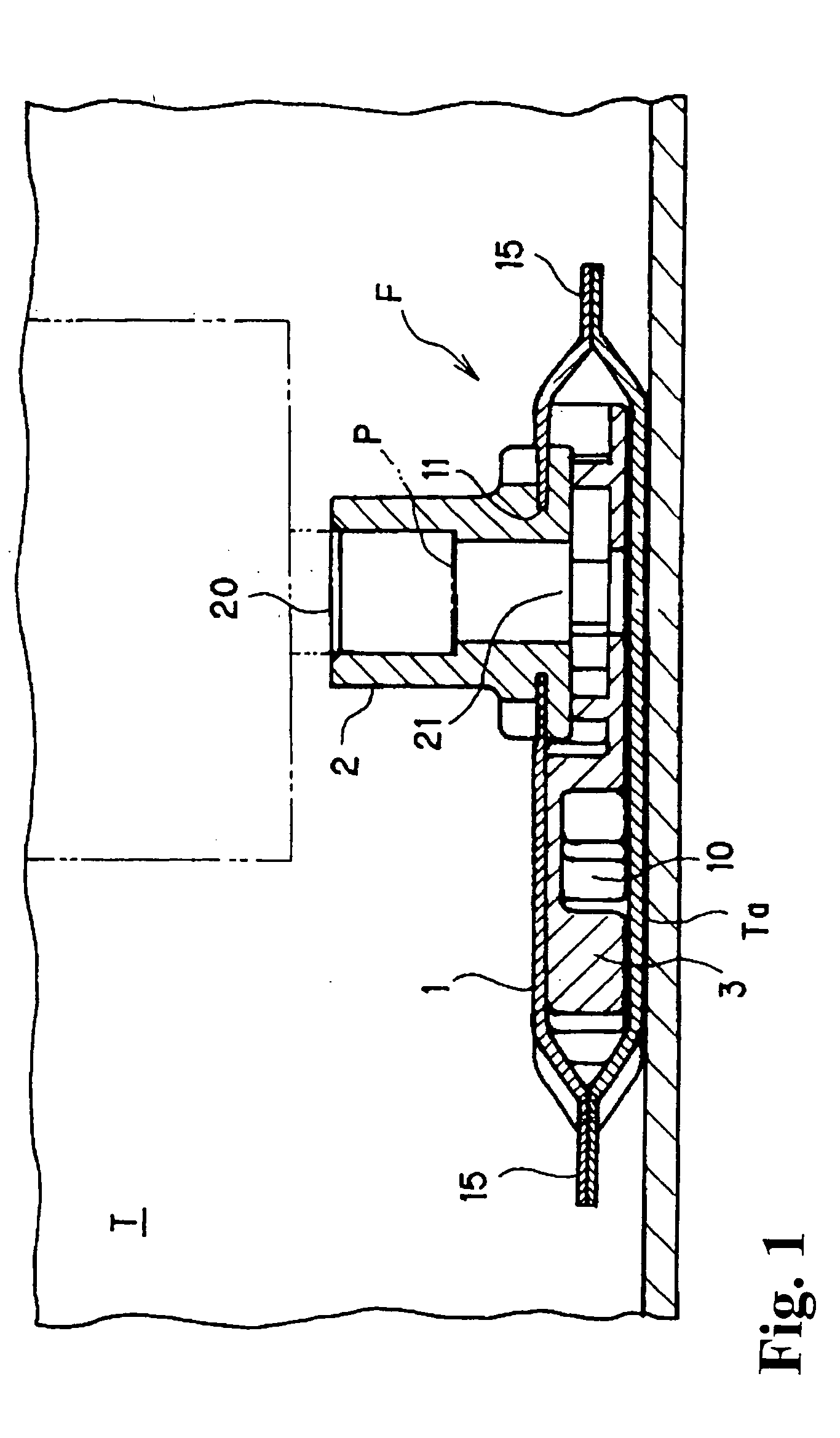
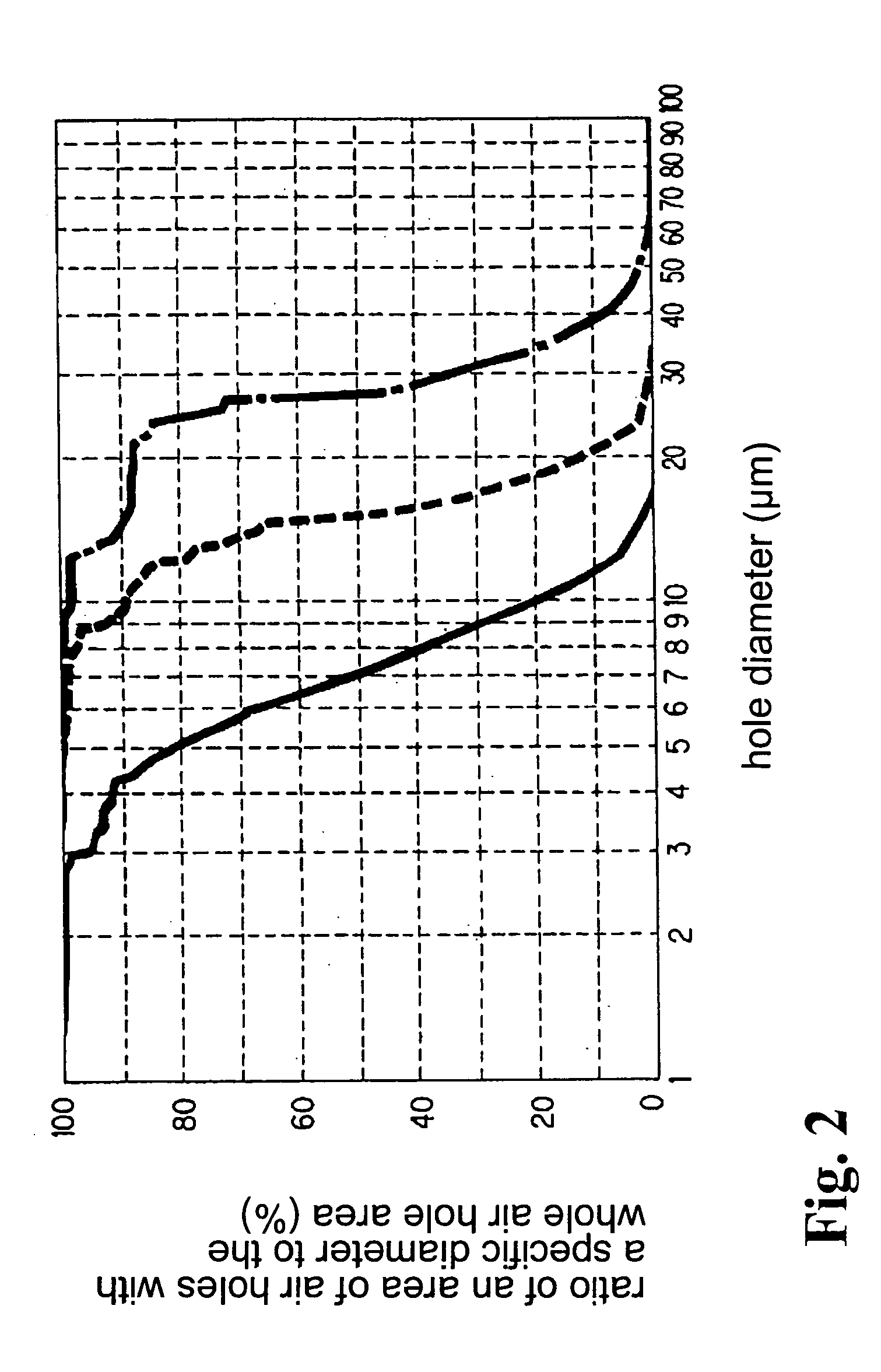
[0028]FIG. 1 is a structural view showing a filter device F in a state attached to a fuel suction opening P inside a fuel tank T. FIG. 3 is a cross-sectional structural view showing an example of a filter member 1 of the filter device F (only cross-sectional structures of an upper side and a lower side of the filter member 1 are shown in FIG. 3, and a description of an interval formation member 3 housed in the filter member 1 is omitted). Also, FIG. 2 is a graph showing characteristics of three non-woven layers 12 formed with a melt blown method in the filter member 1.

[0029] The fuel filter device F according to the embodiment is attached to the fuel suction opening P inside the fuel tank T of an automobile, a motorcycle, and the like, for preventing water or a foreign material from entering fuel transferred to an internal combustion engine through the fuel suction opening P. ...


PUM

PropertyMeasurementUnit
Diameteraaaaaaaaaa
Diameteraaaaaaaaaa
Diameteraaaaaaaaaa

Abstract

A filter member includes at least two non-woven layers, wherein one non-woven layer has air holes with an average diameter different from those of the other non-woven layer. Among the non-woven layers, the non-woven layer located on an inner side of the filter member has the air holes with the average diameter smaller than those of the non-woven layers located on an outer side of the non-woven layer. Also, the non-woven layers are formed with a melt blown method, so that the filtering slope becomes gentle. In the fuel filter device, it is possible to reduce clogging of the filter member as little as possible while improving the filtering accuracy of the filter member.

Description

BACKGROUND OF THE INVENTION AND RELATED ART STATEMENT [0001] The present invention relates to a fuel filter device to be attached to a fuel suction opening inside a fuel tank. [0002] Fuel inside a fuel tank is transferred to an internal combustion engine through a suction pipe disposed inside the fuel tank and the like. In order to remove water and a foreign material from fuel not to move to a fuel pump, a filter device is attached to a fuel suction opening of the suction pipe. As a filter device like this, there is a filter device shown in Patent Reference 1. [0003] This type of filter device includes a bag-shaped filter member having an inner space communicating with the fuel suction opening. Such a filter member includes a non-woven layer formed with a span bond method inside the outermost layer formed of an extruded mesh, and a non-woven layer formed with a melt blown method inside the non-woven layer. [0004] Such a filter device tends to have a large difference between an avera...

Claims


Application Information

Patent Timeline
IPC IPC(8): B01D35/02F02M37/22B01D35/027B01D39/16
CPCB01D35/0273F02M2037/228B01D2201/188F02M37/50B01D35/027
Inventor SATO, HIROJI
Owner NIFCO INC
Why Eureka
Try Eureka