Recording apparatus

a recording head and a technology for recording equipment, applied in the direction of printing mechanisms, power drive mechanisms, printing, etc., can solve the problems of damage to the recording head, and achieve the effects of reducing the number of parts, simple arrangement, and convenient design

Inactive Publication Date: 2007-12-18
SEIKO EPSON CORP
View PDF7 Cites 6 Cited by
  • Summary
  • Abstract
  • Description
  • Claims
  • Application Information

AI Technical Summary

Benefits of technology

[0013]Therefore, it is an object of the present invention to provide a recording apparatus and a liquid emitting apparatus, which are capable of overcoming the above drawbacks accompanying the conventional art. The above and other objects can be achieved by combinations described in the independent claims. More specifically, it is an object of the present invention to provide a recording apparatus and a liquid emitting apparatus that can ensures a distance between a recording head and a medium for which recording is performed in an appropriate manner and can perform high-quality printing. The dependent claims define further advantageous and exemplary combinations of the present invention.

Problems solved by technology

The PG operation lever 203 has to be operated by a user depending on the type of the medium, thus causing a trouble.
In this case, the recording head may be damaged, as disclosed in Japanese Patent Application Laying-Open 2002-192782, for example.

Method used


Image

  • Recording apparatus
  • Recording apparatus
  • Recording apparatus

Examples


Embodiment Construction

[0053]The invention will now be described based on the preferred embodiments, which do not intend to limit the scope of the present invention, but exemplify the invention. All of the features and the combinations thereof described in the embodiment are not necessarily essential to the invention.

[0054]In the following description, an embodiment of a liquid emitting apparatus according to the present invention is described referring to an ink-jet type printer that is an exemplary liquid emitting apparatus of the present invention, based on the drawings.

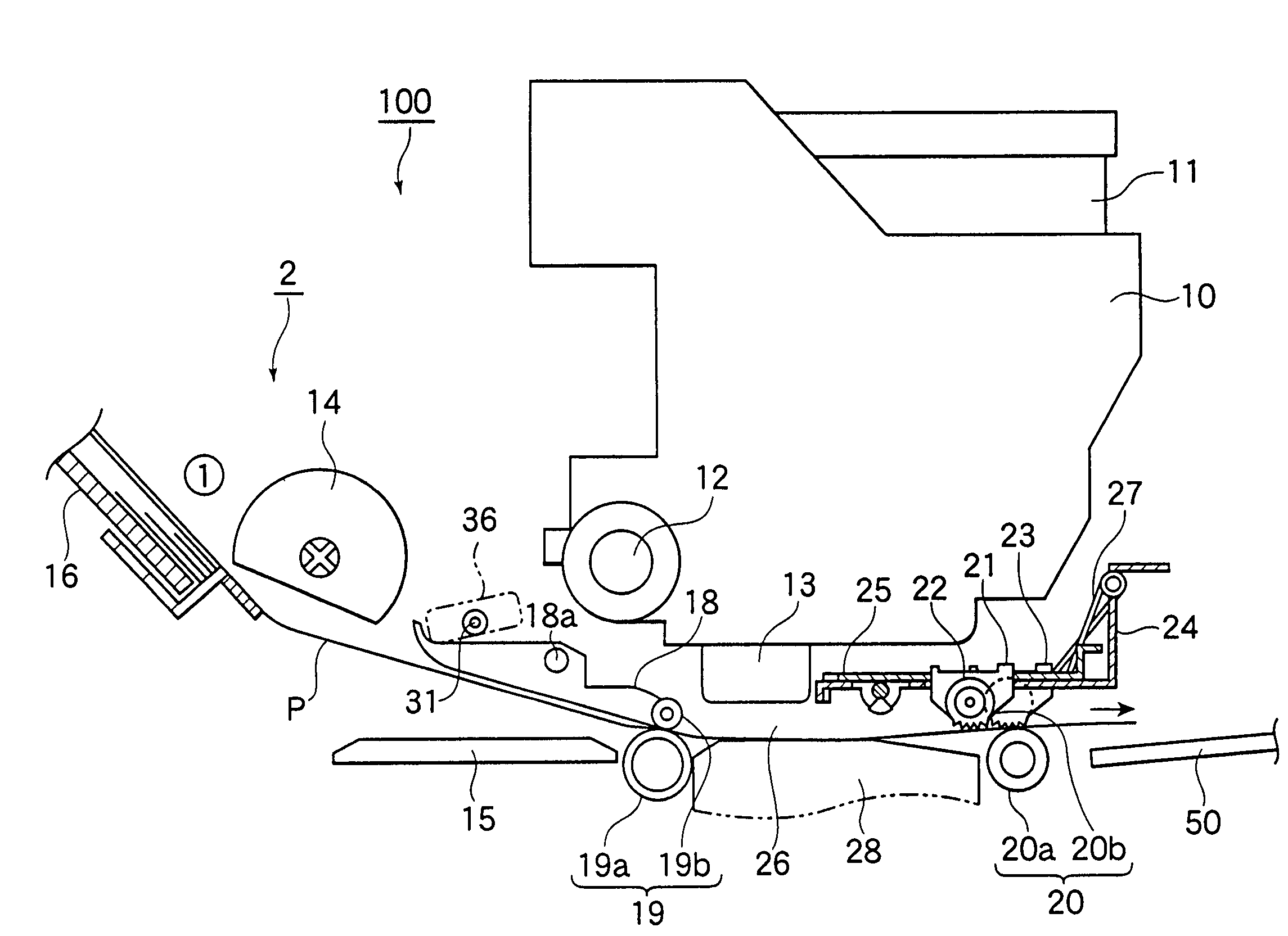
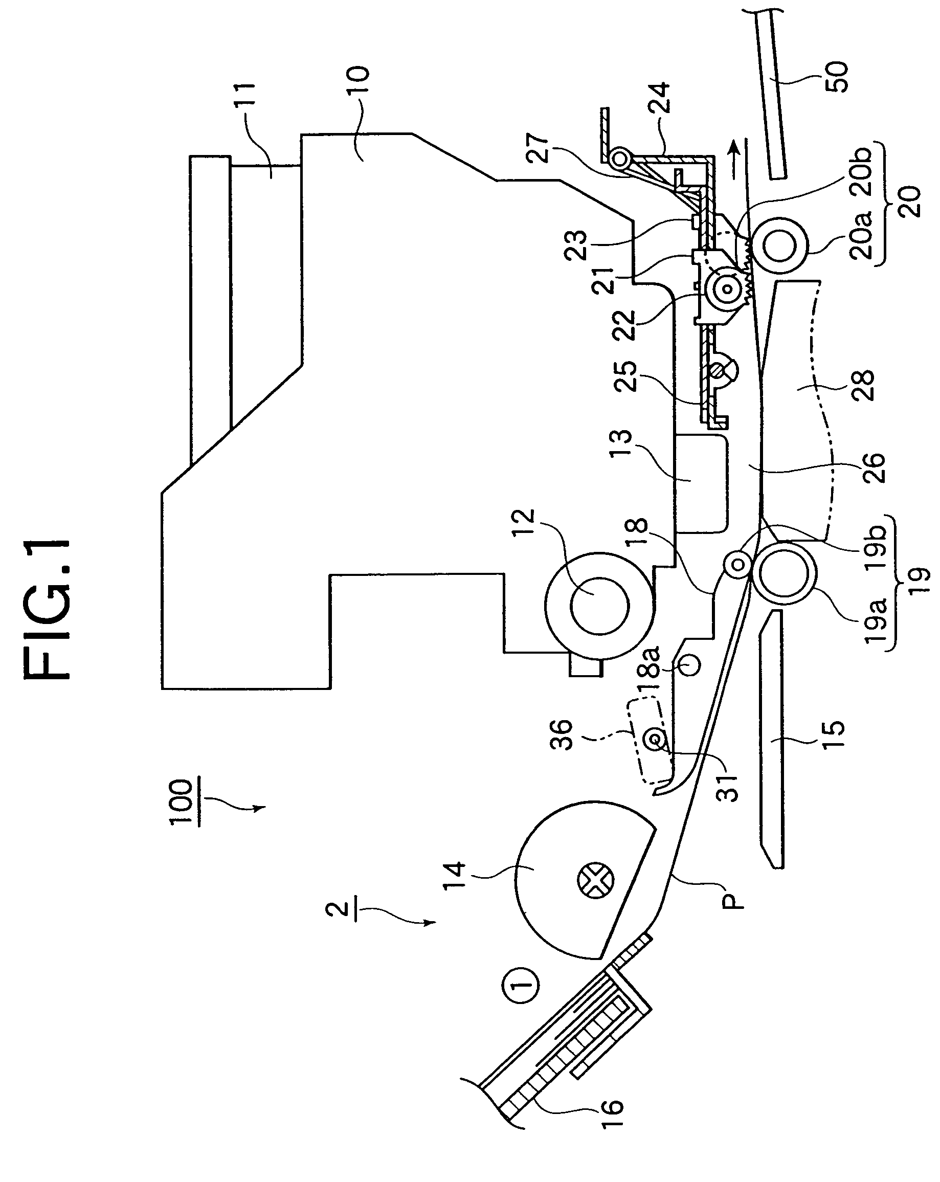
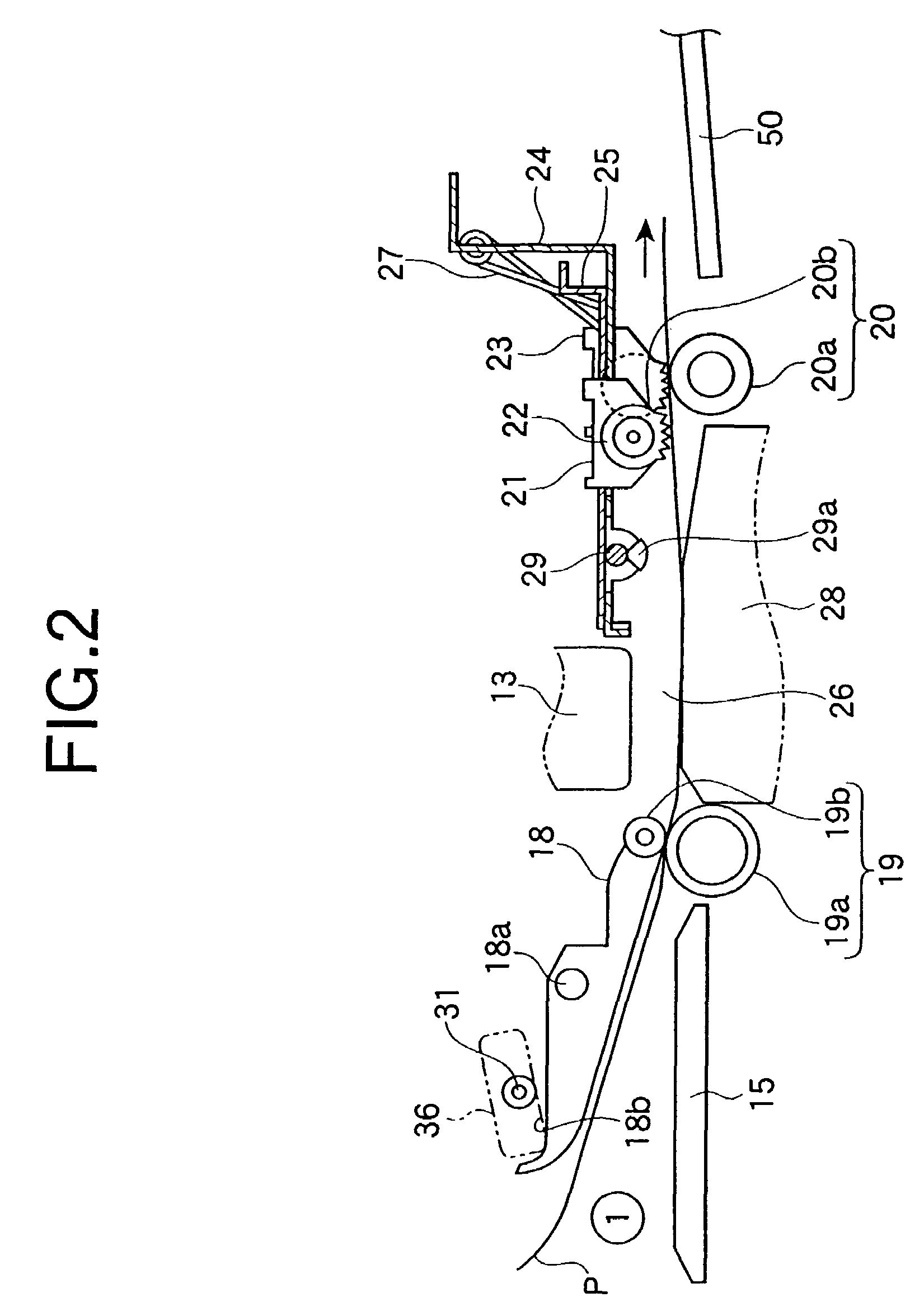
[0055]Referring to FIGS. 1-3, an ink-jet type printer 100 (hereinafter, referred to as a “printer”) as an exemplary recording apparatus according to an embodiment of the present invention is described. FIG. 1 is a cross-sectional view of the printer 100 seen from the side thereof; FIG. 2 is a cross-sectional view of the printer 100 showing a state in which printing is performed for paper by using the first transfer path (1); and FIG. 3 ...


PUM


Abstract

A recording apparatus includes: a feeder, provided in an upstream in a transfer path for transferring a medium, for feeding the medium to a downstream in the transfer path one by one, the medium being stacked at an angle; a recording head, provided in the downstream of the feeder, for performing recording for the medium; a carriage, on which the recording head is mounted, for reciprocating in a main scanning direction along a carriage guide axis; a transfer roller for transferring the medium by rotating, the transfer roller including a transfer-driving roller and a transfer-driven roller; a stacker having a medium-placed surface, the stacker being positioned at a first position allowing the medium to be substantially horizontally fed from the medium-placed surface to a position under the recording head and be substantially horizontally discharged from the position under the recording head onto the medium-placed surface, or a second position for receiving and stacking the medium fed by the feeder, the second position being on a lower level than the first position, the medium-placed surface being arranged substantially horizontally when the stacker is positioned at the first position and is arranged at an angle when the stacker is positioned at the second position; and a first link mechanism for displacing the stacker to cause the carriage guide axis to displace. The carriage guide axis can be displaced upward and is prevented from moving downward when the stacker is positioned at the first position.

Description

[0001]This application is a continuation of U.S. application Ser. No. 10 / 395,642 filed on Mar. 24, 2003, now issued as U.S. Pat. No. 6,814,436.[0002]This patent application claims priority from Japanese patent applications Nos. 2002-82990 filed on Mar. 25, 2002 and 2003-60688 filed on Mar. 6, 2003, the contents of which are incorporated herein by reference.BACKGROUND OF THE INVENTION[0003]1. Field of the Invention[0004]The present invention relates to a recording apparatus for performing recording for recording medium or paper by emitting ink on the recording medium, such as an ink-jet type recording apparatus, and a liquid emitting apparatus for emitting liquid onto a medium to make the liquid adhere to the medium.[0005]The term “liquid emitting apparatus” is used for referring not only to a recording apparatus, having an ink-jet type recording head for emitting ink from the recording head so as to perform recording for a recording medium, such as a printer, a copier and a facsimil...

Claims


Application Information

Patent Timeline
Patent Type & Authority Patents(United States)
IPC IPC(8): B41J2/01B41J11/36B41J13/00B41J13/02B41J13/10B41J25/308
CPCB41J13/0063B41J25/3088B41J25/308B41J13/103
Inventor ANAMI, AKIRAOKI, NARIHIROSHIOTA, TAKAYUKIOTSUKA, KAZUO
Owner SEIKO EPSON CORP
Why Eureka
Try Eureka