Eureka AIR delivers breakthrough ideas for toughest innovation challenges, trusted by R&D personnel around the world.

Telescoping reading light

a reading light and telescoping technology, applied in the field of portable clip-on reading lights, can solve the problems of reduced battery life, frequent battery replacement, and easy shock of bulbs, and achieve the effects of reducing eye strain, promoting long-term reading, and low power consumption

Inactive Publication Date: 2007-12-18
SUNRICH MANUFACTORY
View PDF10 Cites 25 Cited by
  • Summary
  • Abstract
  • Description
  • Claims
  • Application Information

AI Technical Summary

Benefits of technology

[0004]It is an object of the invention to provide a clip-on reading light with increased bulb life.
[0005]It is a further object to provide a clip-on reading light which has increased battery life.
[0006]It is yet another object to provide a clip-on reading light with improved illumination.
[0007]It is yet another object to provide a clip-on reading light that is compact and light weight.
[0009]Utilizing the present invention, a compact portable reading light is provided with an articulatable light that not only illuminates a page but which is rugged, and is low power consuming yet provides particularly bright white light without substantial dimming, for promoting long term reading with limited eye strain. Incorporating the telescoping arm within the housing also provides a compact device since the arm is stored within the housing when not in use.

Problems solved by technology

Generally, such lights are popular but they do suffer from several drawbacks.
Typically, illumination is provided by an incandescent bulb which itself has a limited life and such bulbs are often sensitive to shock during handling and are also difficult to replace.
In addition, power consumption is rather high which may result in reduced battery life and therefore frequent battery replacement.
Often, the bulb is somewhat underpowered and therefore the amount of illumination may dim significantly over time leading to possible eye strain.

Method used


Image

  • Telescoping reading light
  • Telescoping reading light
  • Telescoping reading light

Examples


Embodiment Construction

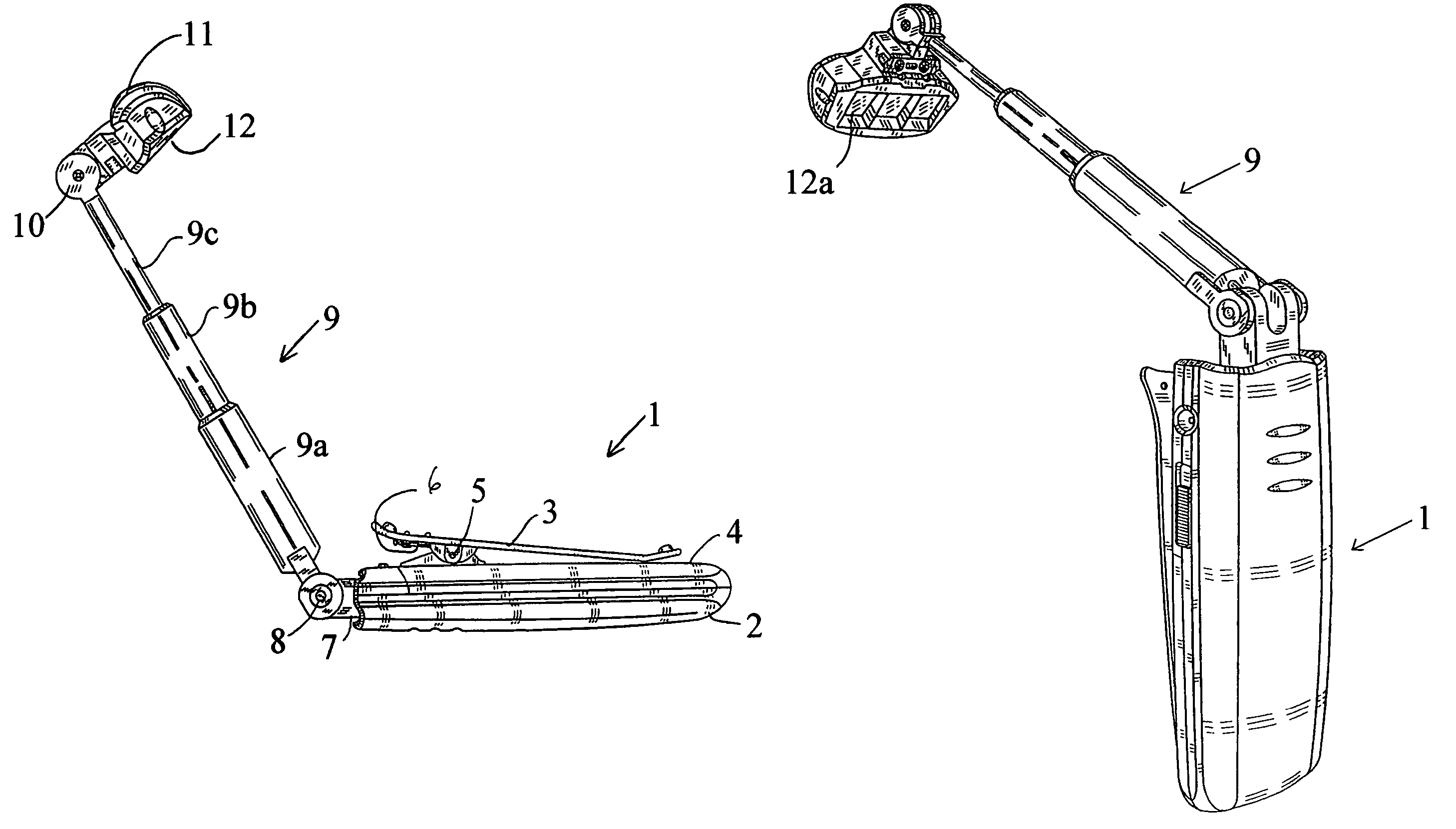
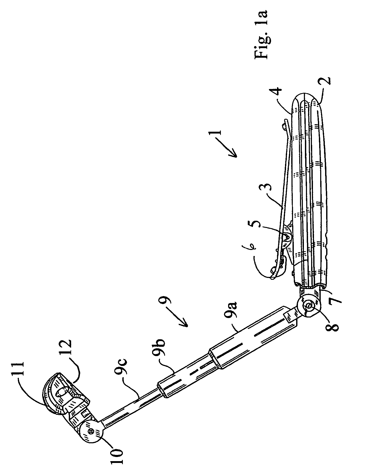
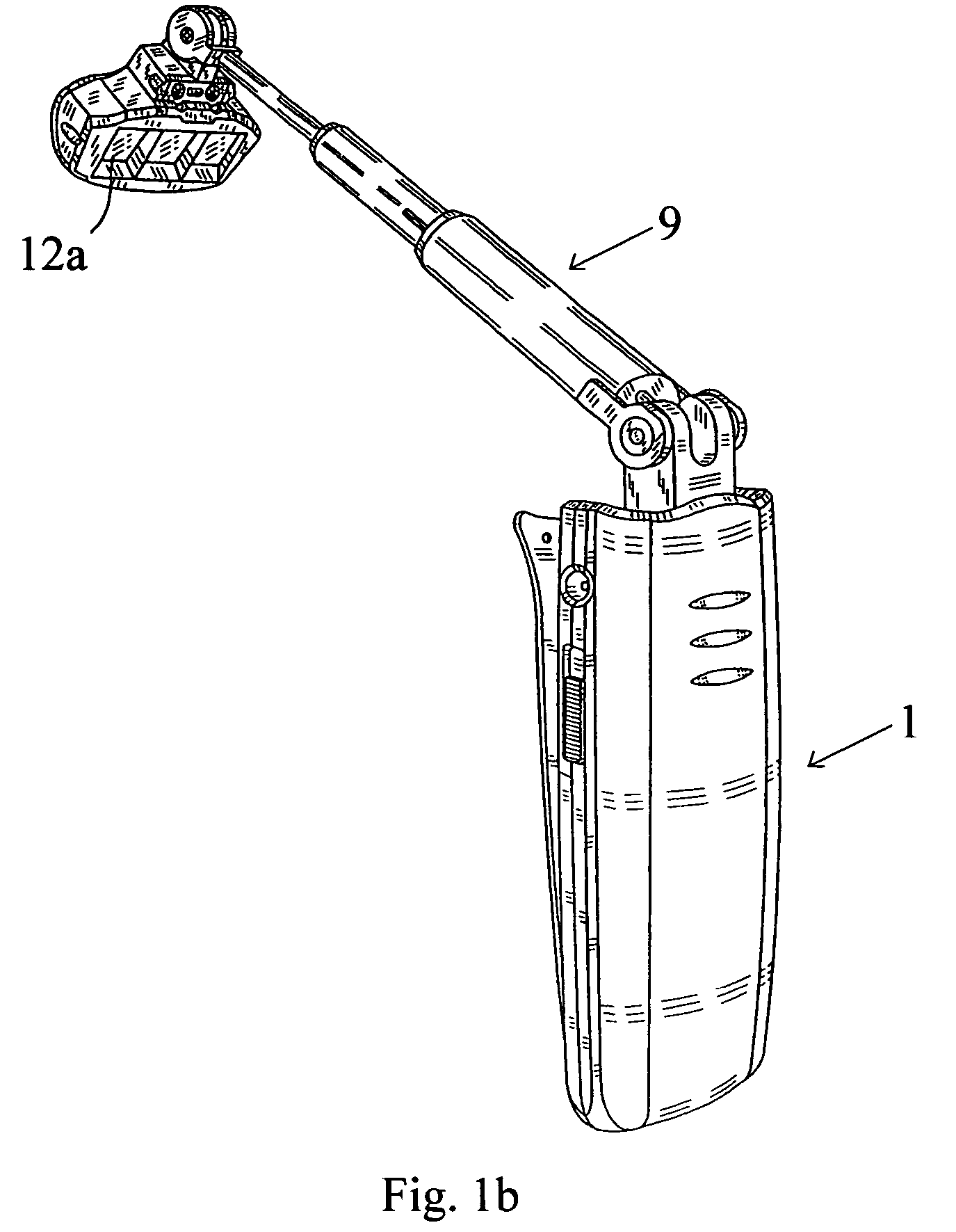
[0018]Referring to FIG. 1a, a portable reading light 1 has a housing 2 having a clip 3 on a side 4 thereof. The clip pivots on a hinge 5 and is biased by a spring 6. The light has a slidable base 7 with a pivot 8 supporting a telescoping arm 9 which has three sections, 9A, 9B and 9C. An outer pivot 10 is located at an outer end of the arm section 9c and has a light support 11 rotatably mounted thereto, within which are disposed three light emitting diodes 12. In FIG. 1a, the portable reading light is shown extended for use. FIG. 1b shows the extended light at an alternate angle, the light emitting diodes 12 and disposed behind individual magnifying lenses 12a which focus the light to improve lighting on the surface illuminated as will be described further below. Using directed light significantly improves readability over the use of LEDs alone.

[0019]Referring to FIG. 2, the portable reading light 1 has the arm 9 stored within the housing 2, and the light support 11 received within a...


PUM


Abstract

A portable reading light has a telescoping arm that is slidable within a housing, the arm having a light source at the end thereof which has one or more light emitting diodes which provide bright light, low power consumption and durability. The light emitting diodes preferably are located in an articulatable light support and disposed adjacent to a focusing lens to better direct and shape the light onto a surface. The arm is mounted to a base assembly slidable within the housing and being telescopically expandable for stabilizing the arm when set for use.

Description

TECHNICAL FIELD[0001]This invention relates to a portable reading light and more particularly to a portable clip-on reading light which has a telescoping arm and improved illumination.BACKGROUND[0002]Portable clip-on reading lights are known. For example, a book light such as that disclosed in U.S. Pat. No. 4,432,042 has a base, an integral clamp from which a vertical lamp bearing arm is mounted to one end with the other end supported by the base. These devices typically comprise a body having means to clip on to a surface, such as a book cover, and include an arm that may be flexible or foldable for aligning a light for illuminating, for example, a page of a book.[0003]Generally, such lights are popular but they do suffer from several drawbacks. Typically, illumination is provided by an incandescent bulb which itself has a limited life and such bulbs are often sensitive to shock during handling and are also difficult to replace. The sensitivity to shock promotes early bulb failure....

Claims


Application Information

Patent Timeline
Patent Type & Authority Patents(United States)
IPC IPC(8): F21V21/00F21L4/02
CPCF21V21/22F21V21/26F21V33/0048F21S9/02F21V21/0885Y10S362/80F21W2131/3005F21Y2101/02F21V21/30F21Y2115/10
Inventor CHAN, WAI HONG
Owner SUNRICH MANUFACTORY
Why Eureka
Eureka Blog
Learn More