
Relative addressing for network elements

Inactive Publication Date: 2007-12-18
CIENA
View PDF30 Cites 81 Cited by
  • Summary
  • Abstract
  • Description
  • Claims
  • Application Information

AI Technical Summary

Problems solved by technology

Network faults disrupt communications between network elements, resulting in lost data traffic.
One drawback of conventional message packet protocols is that it may take longer than desired for the network to perform the provisioning and configuration process to determine the new topology and / or assign new addresses.
This may result, for example, in lost traffic during the provisioning and configuration process.
The time required to negotiate and assign new addresses also limits the ability of the system to make electrical equipment switches or line equipment switches on sub-sections of the network.

Method used


Image

  • Relative addressing for network elements
  • Relative addressing for network elements
  • Relative addressing for network elements

Examples


Embodiment Construction

[0022]The figures depict a preferred embodiment of the present invention for purposes of illustration only. One of skill in the art will readily recognize from the following discussion that alternative embodiments of the structures and methods disclosed herein may be employed without departing from the principles of the claimed invention.

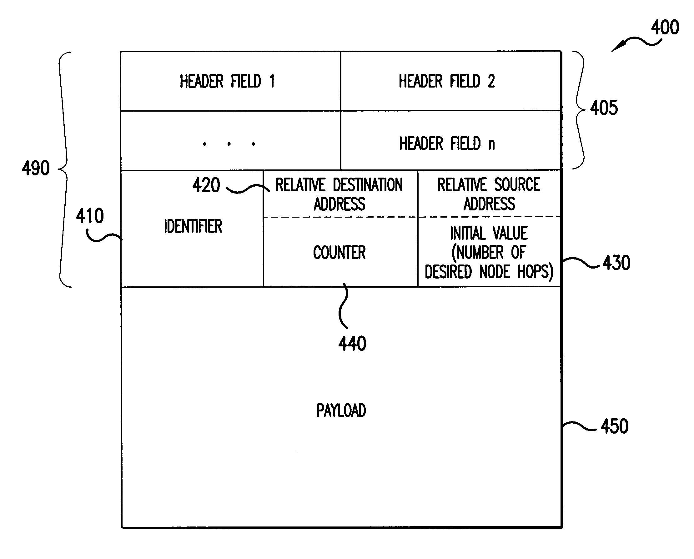
[0023]FIG. 4 shows an embodiment of a relative address protocol 400 of the present invention. The relative address protocol 400 of the present invention may be used for communicating message packets along a portion of a network acting as a network chain of nodes coupled by data links. It will be understood that chain networks include sections of networks that function like linear chain networks over a portion of the network. As used in this application, the term “node” includes the broad meaning that a node is a point in a network where at least two data communication lines are interconnected. This includes conventional network nodes that couple dat...


PUM


Abstract

A relative address protocol for communicating message packets along a linear chain network or quasi-linear chain network is disclosed. The protocol includes a relative destination address field that includes a counter having a preselected initial value at a source node. The initial value is a function of the desired number of node hops that the message packet should travel from the source node. The counter is adjusted in value at each subsequent node by a preselected step in value. When the counter value reaches a trigger value the message packet is accepted by a destination node. In a preferred embodiment, a relative source address field stores the initial value so that the destination node may return a status message to the source node.

Description

RELATED APPLICATIONS[0001]This application claims the benefit of U.S. provisional application Ser. No. 60 / 151,583, “Relative Addressing For Network Elements,” by inventor Hon Wah Chin, filed Aug. 30, 1999, the entire contents of which are hereby incorporated by reference.BACKGROUND OF THE INVENTION[0002]1. Field of the Invention[0003]The present invention relates generally to address protocols for transmitting information packets between the nodes of a network and to methods of network fault detection and isolation.[0004]2. Description of Background Art[0005]Packet data networks, such as optical networks and computer networks, have network nodes coupled by data links. There are a variety of different network topologies, such as linear, branched, mesh, and ring topologies. Packet data networks transmit data to network nodes in the form of message packets. Each message packet comprises a protocol data unit (PDU) that includes a message body (also known as the payload) and a header. Th...

Claims


Application Information

Patent Timeline
IPC IPC(8): G06F15/16G06F15/173H04L12/28
CPCH04L45/00H04L45/34H04L45/20
Inventor CHIN, HON WAH
Owner CIENA
Learn More