Trigger sprayer venting system with reduced drag on vent piston

a technology of venting system and trigger sprayer, which is applied in the direction of transportation and packaging, single-unit apparatus, liquid transferring devices, etc., can solve the problems of liquid leaking from the container through the vent hole, valve is no longer able to immediately reposition itself over the vent hole, and the diaphragm valve is repeated displacement, etc., to achieve the effect of reducing the swelling of the vent piston

Active Publication Date: 2007-12-25
WESTROCK DISPENSING SYST
View PDF15 Cites 7 Cited by
  • Summary
  • Abstract
  • Description
  • Claims
  • Application Information

AI Technical Summary

Benefits of technology

[0013]The present invention overcomes disadvantages associated with prior art venting systems of trigger sprayers by providing an improved trigger sprayer venting system that vents air to the liquid container connected to the trigger sprayer and prevents liquid from leaking through the venting system should the trigger sprayer and liquid container be turned on one side, where the venting system eliminates the undesirable appearance of the vent plunger or vent piston employed in the prior art, and the venting system eliminates the problem of the vent piston sticking in the vent chamber by eliminating swelling of the vent piston and the vent chamber wall.
[0016]The vent chamber is formed on the sprayer housing around the pump chamber of the trigger sprayer. The vent chamber has a cylindrical side wall that extends around and surrounds the pump chamber. This coaxial positioning of the pump chamber and vent chamber relative to each other eliminates the undesirable appearance of the vent plunger or vent piston rod of the trigger sprayer. A vent hole is provided in the sidewall of the vent chamber. The vent hole communicates the interior volume of the vent chamber with the interior of the liquid container connected to the trigger sprayer.
[0018]With the vent chamber being coaxial with the pump chamber, the vent piston is formed coaxially around the pump piston. The vent piston is formed of the same resilient material as the pump piston. In a first position of the vent piston relative to the vent chamber, the peripheral surface of the vent piston engages in a sealing engagement with the necked down portion of the vent chamber interior surface at the vent chamber forward end. This seals the interior of the vent chamber from the exterior environment of the trigger sprayer, and prevents unintended liquid leakage from the liquid container attached to the trigger sprayer through the vent chamber.
[0019]On actuation of the liquid pump, the vent piston moves with the pump piston. The vent piston moves away from the necked down portion of the vent chamber interior surface having the smaller interior diameter, toward the rearward end of the vent chamber. This movement of the vent piston causes the force of engagement of the peripheral surface of the vent piston against the interior surface of the vent chamber to decrease, thereby reducing the drag on the vent piston peripheral surface as the vent piston moves from the vent chamber forward end toward the vent chamber rearward end and through the larger interior diameter portion of the vent chamber. This reduced drag prevents swelling of the peripheral surface of the vent piston and / or the vent chamber interior surface, and prevents binding of the vent piston in the vent chamber.

Problems solved by technology

However, this prior art venting system has been found to be disadvantaged in that repeated use of the trigger sprayer causes repeated displacement of the diaphragm valve from the sprayer vent hole.
The resiliency of the diaphragm valve is effected by these repeated displacements and the valve is no longer able to immediately reposition itself over the vent hole once the plunger is retracted from the vent hole.
This can result in liquid leaking from the container through the vent hole should the container and trigger sprayer be knocked over on one side before the diaphragm valve repositions itself over the vent hole.
In addition, the plunger projecting from the piston rod is considered by many to detract from the appearance of the sprayer and is undesirable.
This venting system has been found to be disadvantaged in that is has the same unappealing appearance of the plunger.
Also, after repeated use of the trigger sprayer, the ribs in the vent cylinder have a tendency to deform the resilient material around the periphery of the vent piston.
This detracts from the ability of the vent piston to seal against the interior surface of the vent cylinder, and can result in leakage of liquid from the liquid container through the vent cylinder.
However, the sliding engagement or rubbing of the vent piston peripheral sealing surface across the cylindrical interior surface of the vent chamber as the trigger sprayer pump is operated often causes swelling of the material of the vent piston.
This swelling of the vent piston can bind the vent piston in the vent chamber, making it difficult or uncomfortable to push the vent piston into the vent chamber, and at times preventing the vent piston from being pushed back out of the vent chamber by the pump spring.

Method used


Image

  • Trigger sprayer venting system with reduced drag on vent piston
  • Trigger sprayer venting system with reduced drag on vent piston
  • Trigger sprayer venting system with reduced drag on vent piston

Examples


Embodiment Construction

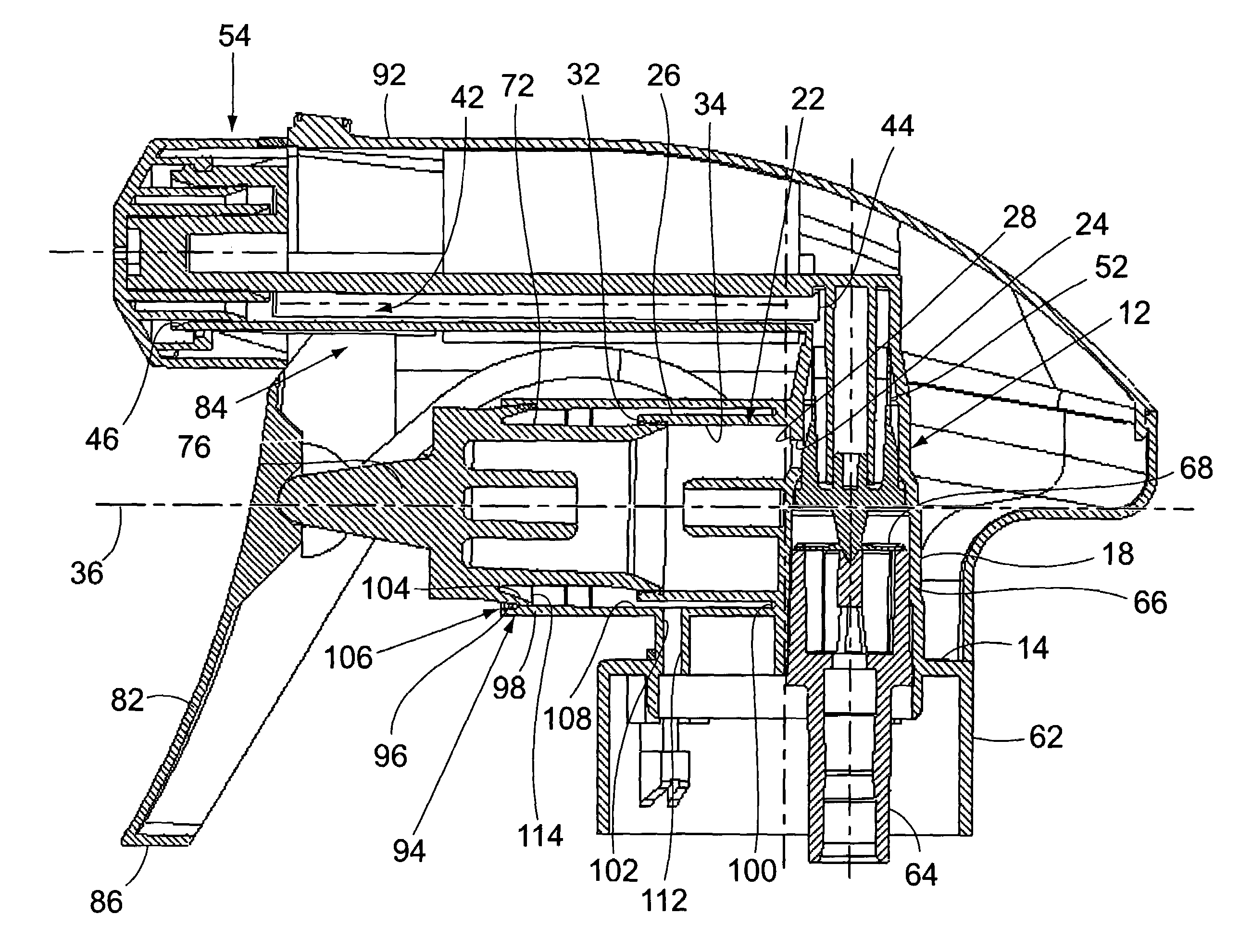
[0025]FIG. 1 shows a side sectioned view of the trigger sprayer of the invention that includes the novel venting system of the invention. Many of the component parts and the details of construction of the trigger sprayer shown in FIG. 1 are common to trigger sprayers of the prior art. Therefore, these will only be described generally. The novel venting system of the invention will be described in more detail. As is typical in the construction of trigger sprayers, most of the component parts are constructed of a plastic material.

[0026]The trigger sprayer comprises a sprayer housing 12 that is molded with many of the component parts of the trigger sprayer. The bottom of the sprayer housing 12 is formed with a circular disk 14. An opening passes through the disk 14 and a liquid supply passage 18 extends upwardly through the sprayer housing from the disk. A pump chamber 22 is formed on the sprayer housing 12 and communicates through a pump port 24 with the liquid supply passage 18.

[0027...


PUM


Abstract

A venting system of a manually operated trigger sprayer vents the interior of a liquid container connected to the trigger sprayer. The trigger sprayer is provided with a vent chamber that surrounds the pump chamber, and a vent piston that surrounds the pump piston. The vent piston is received in the vent chamber for reciprocating movements between a vent closed and vent opened position in the vent chamber, and the vent chamber having two different interior diameter sections with a larger interior diameter section reducing drag on the vent piston when the vent piston is moved to the vent opened position.

Description

[0001]This patent application is a continuation-in-part of patent application Ser. No. 10 / 961,286, which was filed on Oct. 8, 2004, and is currently pending.BACKGROUND OF THE INVENTION[0002](1) Field of the Invention[0003]The present invention pertains to a venting system for a manually operated, liquid dispensing trigger sprayer. More specifically, the present invention pertains to improvements to a venting system of a manually operated trigger sprayer that vents the interior of a liquid container connected to the trigger sprayer. For the most part, the construction of the trigger sprayer is typical. The improvement comprises a vent chamber that surrounds the pump chamber and a vent piston that surrounds the pump piston. The vent piston is received in the vent chamber for reciprocating movements with the pump piston in the pump chamber. The reciprocating movement of the vent piston alternatively opens the vent chamber to the exterior environment of the trigger sprayer and thereby v...

Claims


Application Information

Patent Timeline
Patent Type & Authority Patents(United States)
IPC IPC(8): B67D5/42B67D7/58B67D7/60
CPCB05B11/0016B05B11/3077B05B11/3074B05B11/3011B05B11/0044B05B11/1011B05B11/1077B05B11/1074
Inventor FOSTER, DONALD D.
Owner WESTROCK DISPENSING SYST
Why Eureka
Try Eureka