Self cleaning shredding device having movable cleaning rings

a shredding device and self-cleaning technology, which is applied in the field of machines, devices or installations, can solve the problems of reducing the efficiency of cutting machinery, even stalling machinery, and attempts to provide mechanisms or means to prevent material wrapping around cutters, and achieve the effect of reducing the noise of impact or against cutters

Inactive Publication Date: 2007-12-25
TERRANCE JAMES PARKE
View PDF6 Cites 8 Cited by
  • Summary
  • Abstract
  • Description
  • Claims
  • Application Information

AI Technical Summary

Benefits of technology

[0004]One problem of existing cutting devices and shredders used in recycling waste or scrap materials for reducing the size of the scrap material or waste material to relatively smaller sized particles is that the strips of material formed as part of the size reduction operation have a tendency to wrap around the cutting assemblies or arrays so as to become wound around and / or entangled in the cutters and shaft on which the cutters are mounted during operation of the device which has the effect of reducing the efficiency of cutting of the machinery or even stalling the machinery if there is an excessive build-up of strips of severed material around the cutters and shafts. Previous attempts at providing mechanisms or means for preventing material wrapping around the cutters or becoming lodged in the cutting assembly or clearing severed material away from the cutters, have not been entirely successful for a variety of reasons. Thus, it is one aim of the present invention to provide a shredding device that has an effective anti-wrapping arrangement for reducing or preventing the amount of material which wraps around the cutting elements and / or shafts to become entangled within the cutting arrays and shafts during use of the cutting device.
[0029]Typically, the spacer ring is provided with a wear surface or wear portion. More typically, the wear surface is a ring, either a complete ring or a partial ring, located at or towards one or both sides of the spacer ring. Even more typically, the wear ring is metallic or is a resilient material made from a foam material, or is a plastically deformable material. Even more typically, the foam material is a sound deadening material for reducing the noise of impact of or against the cutters. Even more typically, the wear portion is made from the same material as the spacer ring or from a material which is more durable or harder than the spacer ring.

Problems solved by technology

One problem of existing cutting devices and shredders used in recycling waste or scrap materials for reducing the size of the scrap material or waste material to relatively smaller sized particles is that the strips of material formed as part of the size reduction operation have a tendency to wrap around the cutting assemblies or arrays so as to become wound around and / or entangled in the cutters and shaft on which the cutters are mounted during operation of the device which has the effect of reducing the efficiency of cutting of the machinery or even stalling the machinery if there is an excessive build-up of strips of severed material around the cutters and shafts.
Previous attempts at providing mechanisms or means for preventing material wrapping around the cutters or becoming lodged in the cutting assembly or clearing severed material away from the cutters, have not been entirely successful for a variety of reasons.
Another problem of existing shredding devices is that the cutters become clogged with partially cut material that adheres to the cutters.
The pressure of partially shredded or shredded material on or around the cutters reduces their efficiency.
Another problem associated with existing shredding devices is that the cutting surfaces of the cutting elements become blunt within a very short period of time by being in constant contact with each other which accelerates the wear of the cutting surfaces and edges.
One reason for the cutting edges or surfaces becoming prematurely blunt is that such cutters are not provided with any self cleaning or self sharpening mechanism to prolong the useful working life of the cutters.
The accumulation of debris from severed material between the cutters accelerates the rate of wear of the cutters.
Another reason for existing cutting assemblies becoming prematurely blunt is that foreign objects contaminating the feed material could become trapped between the cutters so that the foreign objects are continually being struck by the rotating cutters of the cutting assembly such as by the foreign objects becoming wedged between adjacent cutters and / or between the cutters and shafts since there was no effective mechanism provided to clean or clear the cutters of such objects.
Again, the wear caused by this situation is accelerated by strips of material being wound around the shafts and / or cutters.
In some cases the cutting devices are damaged by the foreign objects, whilst in others the cutting devices stall.

Method used


Image

  • Self cleaning shredding device having movable cleaning rings
  • Self cleaning shredding device having movable cleaning rings
  • Self cleaning shredding device having movable cleaning rings

Examples


Embodiment Construction

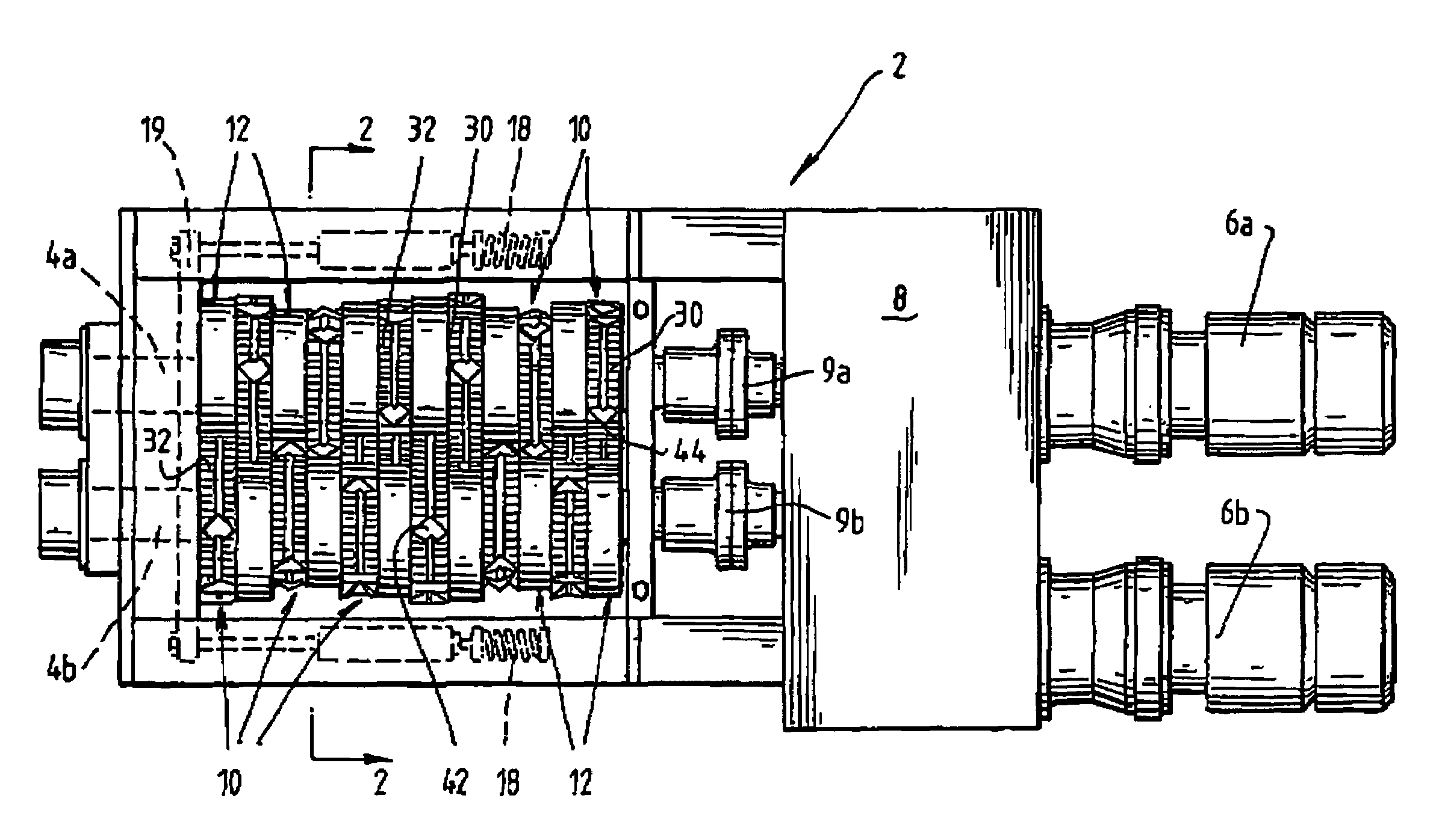
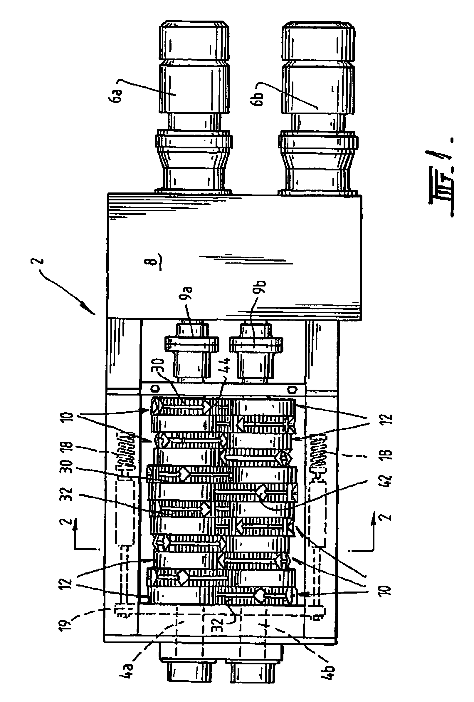
[0041]In FIG. 1 there is shown one form of a shredder or shredding machine, generally denoted as 2, suitable for shredding used motor vehicle tires. Briefly, shredder 2 includes a pair of driven counter-rotating spaced apart shafts 4a,4b arranged in substantially parallel relationship to each other. Shafts 4a,4b are driven by suitable motors 6a,6b arranged in substantial parallel relationship through a suitable transmission 8, such as electric or hydraulic motors and mechanical gearboxes. Couplings 9a, 9b join shafts 4a, 4b to gearbox / transmission 8.

[0042]A plurality of rotary cutters 10 are located on one of the shafts 4a arranged alternately with a plurality of spacer rings 12 to form an alternating sequence of cutters 10 and spacers 12 in a row on this shaft. A second shaft 4b is also provided with a plurality of cutters 10 and spacers 12 alternately arranged thereon to also form an alternating sequence of cutters and spacers in a row. The cutters 10 on one shaft 4a are arranged ...


PUM


Abstract

A self cleaning cutting assembly is provided, having an array of counter rotating cutters in which a plurality of cutters rotating in a first direction are mounted on a first shaft and a plurality of second cutters are mounted on a second shaft for rotating in an opposite direction. The array of cutters is provided with a plurality of clearing or cleaning rings located alternately with the cutters on each shaft. The cutting array is kept clear of debris or partially cut material by movement of the clearing or cutting rings against adjacent cutters. Movement of the clearing or cleaning rings is a combination of rotary motion and linear motion, in which the linear motion is imparted by the cutter located opposite the cleaning ring striking the cleaning rings so as to push the cleaning ring beyond the position of the widest part of the cutter to completely dislodge material from the cutter.

Description

[0001]The present invention relates generally to machinery, devices or installations used in the material treatment industries, particularly in the recycling and waste disposal industries. In particular the present invention relates to apparatus, appliances and assemblies that may be used to cut, crush, pulverise, comminute or otherwise reduce in size a wide variety of different materials, particularly waste or scrap materials, so as to convert the waste or scrap materials into a size which is more usable or useful, such as for example, for use in further processing in the manufacture of recycled goods or of a size which is easier to dispose of or of a size for more advantageous final disposal of the waste or scrap material, either in land fill, for recycling or for consumption, such as a fuel or the like. Even more particularly the present invention relates to an apparatus or device provided with a cutting assembly having one or more cutting elements arranged in cutting arrays or s...

Claims


Application Information

Patent Timeline
Patent Type & Authority Patents(United States)
IPC IPC(8): B02C1/08B02C13/20B02C7/04B02C18/00B02C18/14B02C18/16B02C18/18B02C18/22B02C18/24
CPCB02C18/142B02C18/16B02C18/182Y10S241/31B02C2201/04B02C2018/164B02C2018/0069
Inventor MATHERS, LEGAL REPRESENTATIVE, KARENPARKE, DECEASED, TERRENCE JAMES
Owner TERRANCE JAMES PARKE
Why Eureka
Try Eureka