Self cleaning shredding device having movable cleaning rings

Inactive Publication Date: 2005-02-24
TERRANCE JAMES PARKE
View PDF6 Cites 26 Cited by
  • Summary
  • Abstract
  • Description
  • Claims
  • Application Information

AI Technical Summary

Benefits of technology

[0017] whereby movement of the cleaning means with respect to the first cutter means caused by contact from the second cutter means maintains the first cutter means in a condition substantially free of the severed relatively smaller size pieces of material thereby reducing or substantially eliminating the r

Problems solved by technology

Even more typically, the shredded pieces have a tendency to curl or wrap around the cutters, particularly due

Method used


Image

  • Self cleaning shredding device having movable cleaning rings
  • Self cleaning shredding device having movable cleaning rings
  • Self cleaning shredding device having movable cleaning rings

Examples


Embodiment Construction

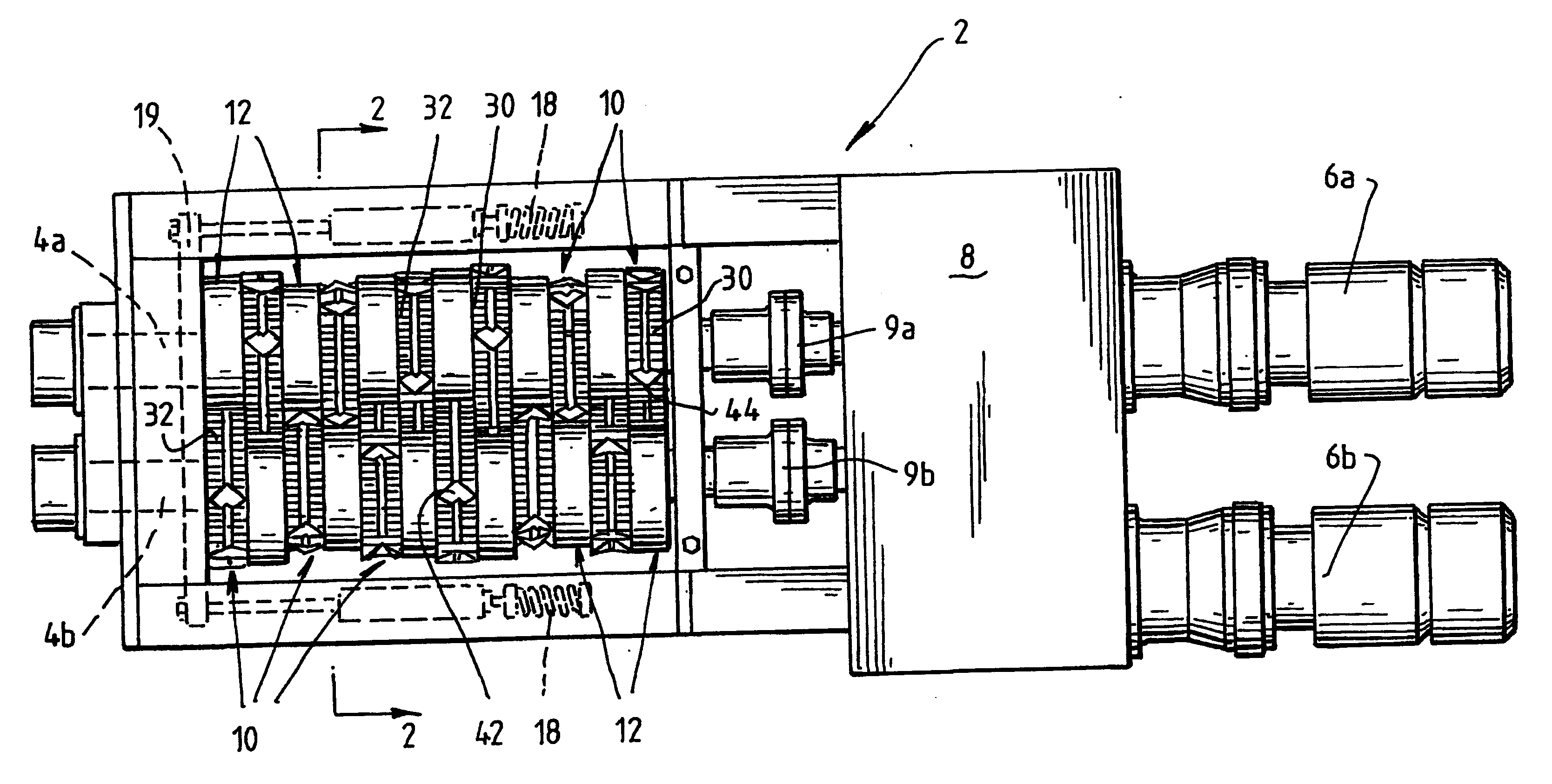
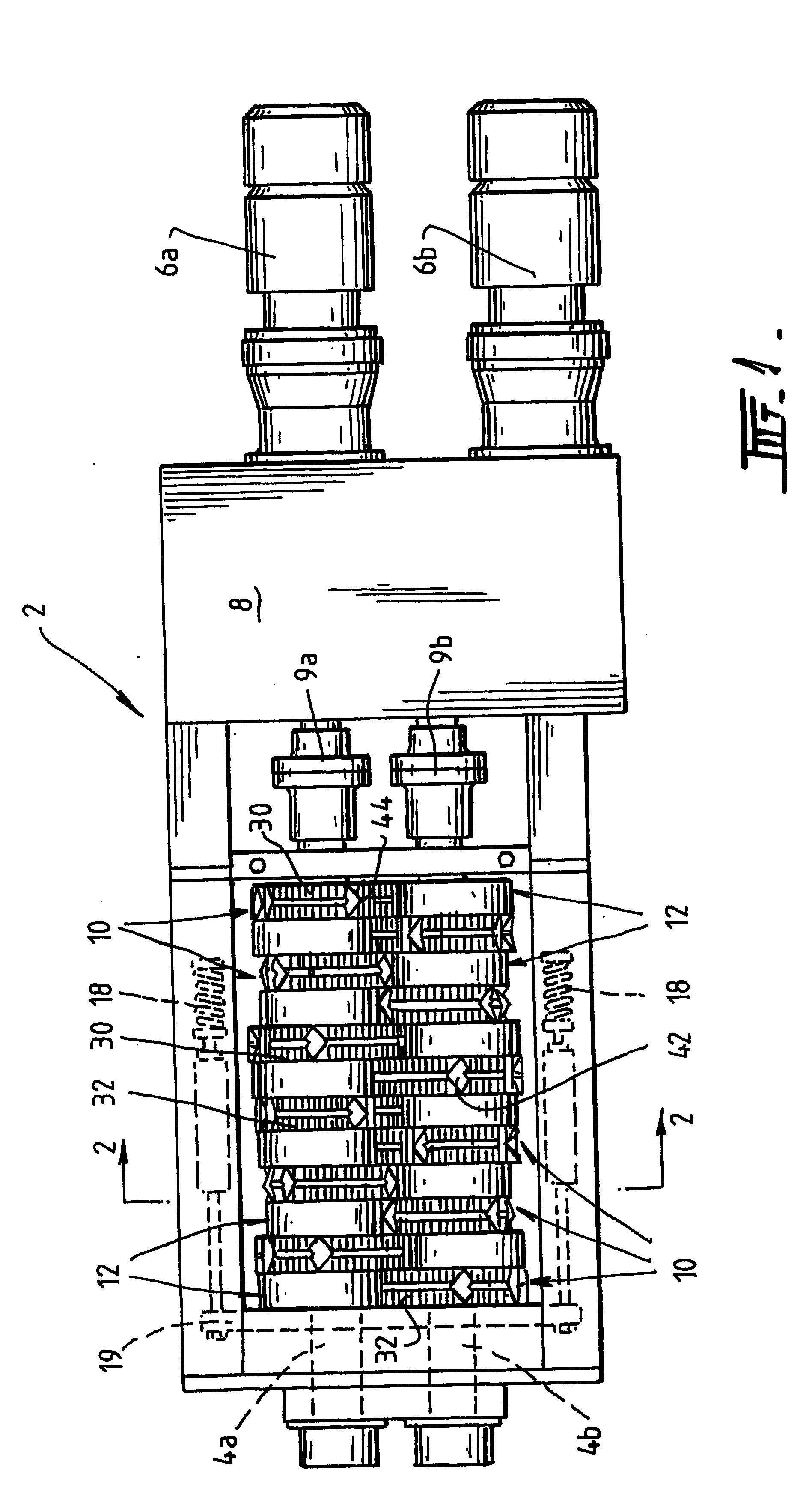
[0041] In FIG. 1 there is shown one form of a shredder or shredding machine, generally denoted as 2, suitable for shredding used motor vehicle tires. Briefly, shredder 2 includes a pair of driven counter-rotating spaced apart shafts 4a,4b arranged in substantially parallel relationship to each other. Shafts 4a,4b are driven by suitable motors 6a,6b arranged in substantial parallel relationship through a suitable transmission 8, such as electric or hydraulic motors and mechanical gearboxes. Couplings 9a, 9b join shafts 4a, 4b to gearbox / transmission 8.

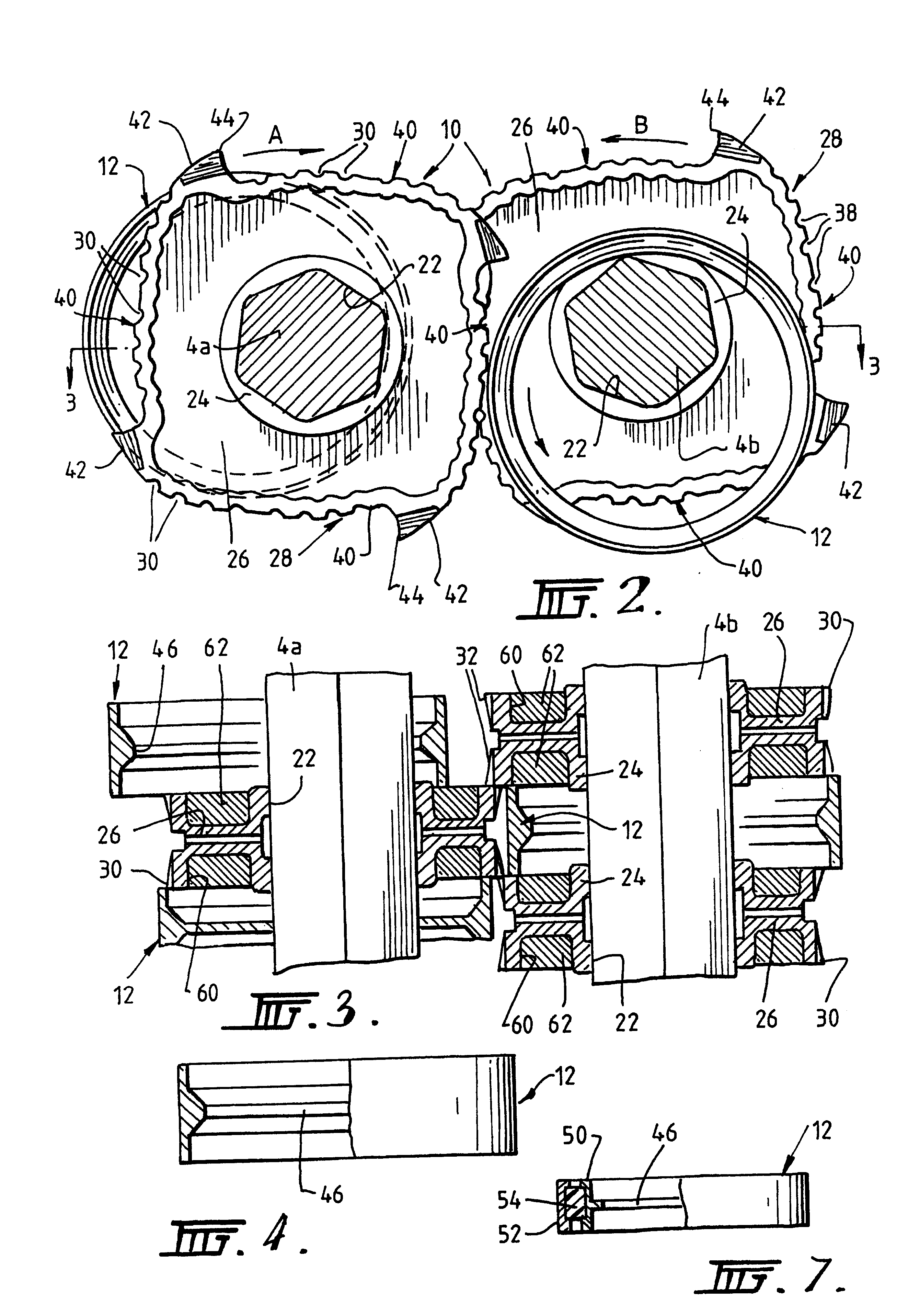
[0042] A plurality of rotary cutters 10 are located on one of the shafts 4a arranged alternately with a plurality of spacer rings 12 to form an alternating sequence of cutters 10 and spacers 12 in a row on this shaft. A second shaft 4b is also provided with a plurality of cutters 10 and spacers 12 alternately arranged thereon to also form an alternating sequence of cutters and spacers in a row. The cutters 10 on one shaft 4a are arrang...


PUM


Abstract

A self cleaning cutting assembly is provided, having an array of counter rotating cutters in which a plurality of cutters rotating in a first direction are mounted on a first shaft and a plurality of second cutters are mounted on a second shaft for rotating in an opposite direction. The array of cutters is provided with a plurality of clearing or cleaning rings located alternately with the cutters on each shaft. The cutting array is kept clear of debris or partially cut material by movement of the clearing or cutting rings against adjacent cutters. Movement of the clearing or cleaning rings is a combination of rotary motion and linear motion, in which the linear motion is imparted by the cutter located opposite the cleaning ring striking the cleaning rings so as to push the cleaning ring beyond the position of the widest part of the cutter to completely dislodge material from the cutter.

Description

[0001] The present invention relates generally to machinery, devices or installations used in the material treatment industries, particularly in the recycling and waste disposal industries. In particular the present invention relates to apparatus, appliances and assemblies that may be used to cut, crush, pulverise, comminute or otherwise reduce in size a wide variety of different materials, particularly waste or scrap materials, so as to convert the waste or scrap materials into a size which is more usable or useful, such as for example, for use in further processing in the manufacture of recycled goods or of a size which is easier to dispose of or of a size for more advantageous final disposal of the waste or scrap material, either in land fill, for recycling or for consumption, such as a fuel or the like. Even more particularly the present invention relates to an apparatus or device provided with a cutting assembly having one or more cutting elements arranged in cutting arrays or ...

Claims


Application Information

Patent Timeline
IPC IPC(8): B02C18/00B02C18/14B02C18/16B02C18/18B02C18/22B02C18/24
CPCB02C18/142B02C18/16B02C18/182Y10S241/31B02C2201/04B02C2018/164B02C2018/0069
Inventor PARKE, TERRENCE JAMES
Owner TERRANCE JAMES PARKE
Why Eureka
Try Eureka