Receiver tube with receiver tubular jacket and parabolic trough collector containing same

Inactive Publication Date: 2008-07-08
SCHOTT AG
View PDF14 Cites 17 Cited by
  • Summary
  • Abstract
  • Description
  • Claims
  • Application Information

AI Technical Summary

Benefits of technology

[0021]In a preferred embodiment of the parabolic trough collector the receiver tube is displaced somewhat relative to the focal point in the direction of the parabolic mirror by a distance equal to about half the spacing between the tubular jacket and the absorber tube. Because of that displacement losses from radiation, which misses

Problems solved by technology

Focusing errors and thus geometrically dependent optical losses occur in parabolic trough collectors due to various factors.
For example, the mirror elements have a certain total shape tolerance or also waviness, which leads to focusing errors.
Last, but not least, wind occurring in the vicinity of the parabolic trough collector leads to deformation of the entire structure and thus to focusing errors.
If the secondary

Method used


Image

  • Receiver tube with receiver tubular jacket and parabolic trough collector containing same
  • Receiver tube with receiver tubular jacket and parabolic trough collector containing same
  • Receiver tube with receiver tubular jacket and parabolic trough collector containing same

Examples


Embodiment Construction

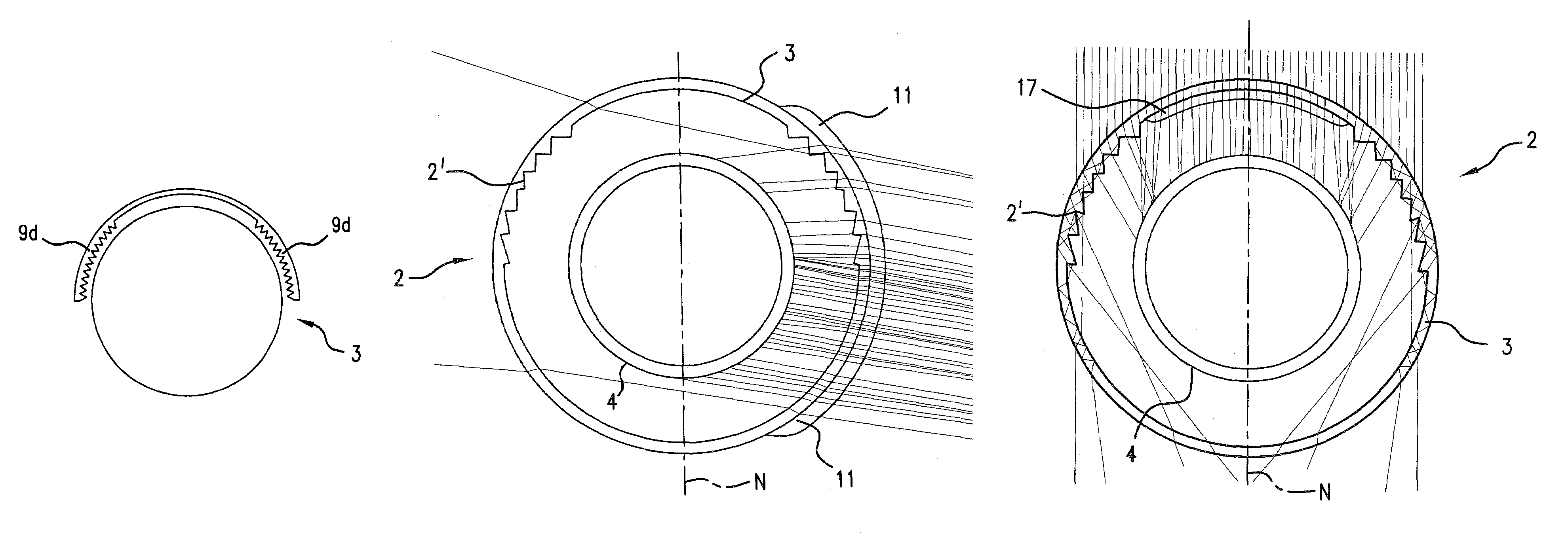
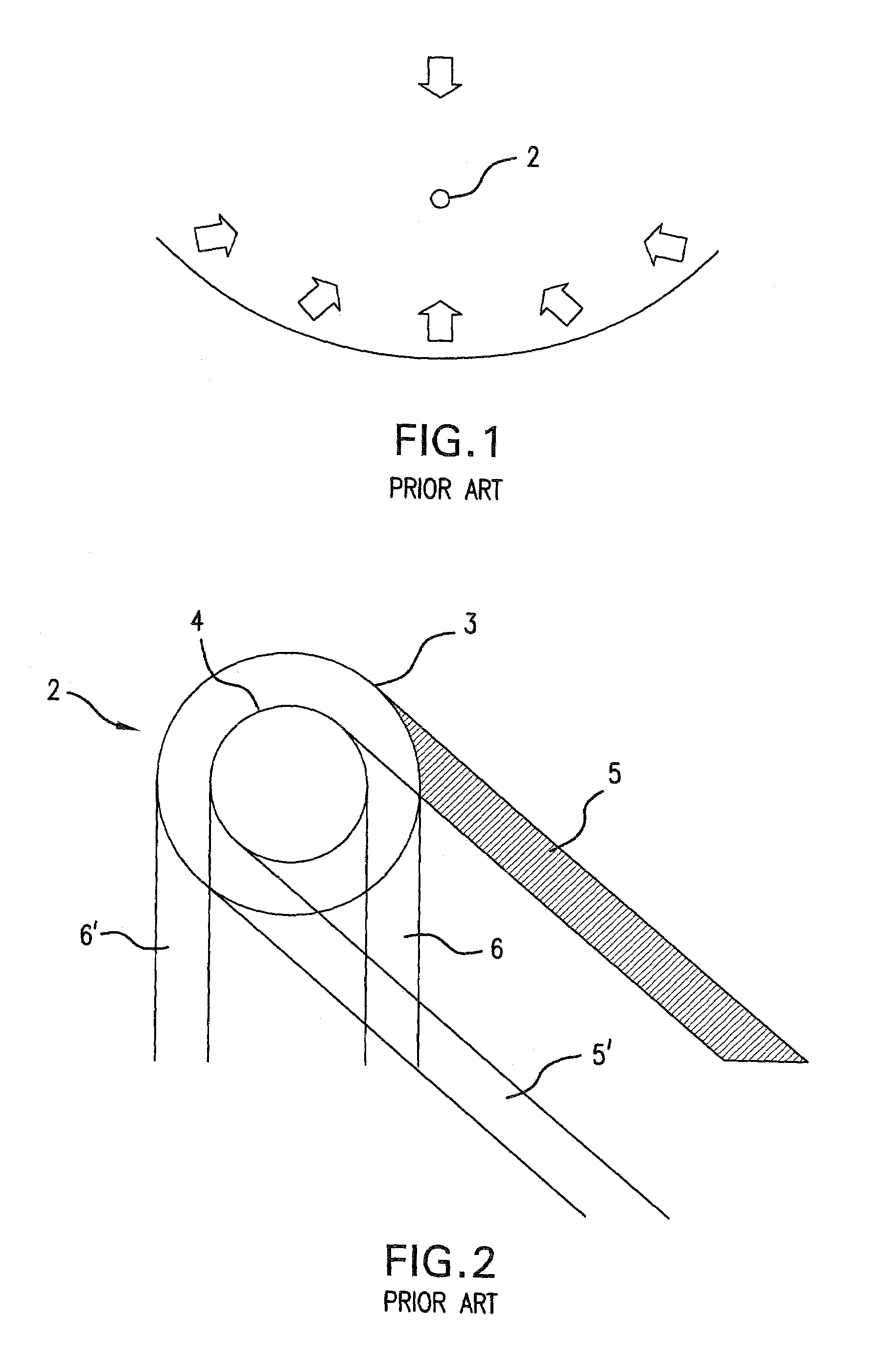
[0035]In FIG. 1 a parabolic mirror 1 and a receiver tube 2 are illustrated. The receiver tube 2 is arranged at the focus of the parabolic mirror 1 in the arrangement shown in FIG. 1. Incident radiation on the side of the receiver tube facing the sun always impinges in the normal direction, since the mirror 1 and the receiver tube 2 are pointed exactly toward the position of the sun. Radiation impinges at an angle between 160° and 180° on the side of the receiver tube 2 facing the mirror. The arrows in FIG. 1 show the incidence angles.

[0036]In FIG. 2 a conventional receiver tube 2 is shown, which comprises an absorber tube 4 and a tubular jacket 3. The radiation beam 5,5′ is a beam, which passes comparatively far from the optic axis of the collector, while the radiation beam6,6′ is a beam, which passes comparatively close to the axis. Both beams pass through the tubular jacket 3 without striking the absorber tube 4.

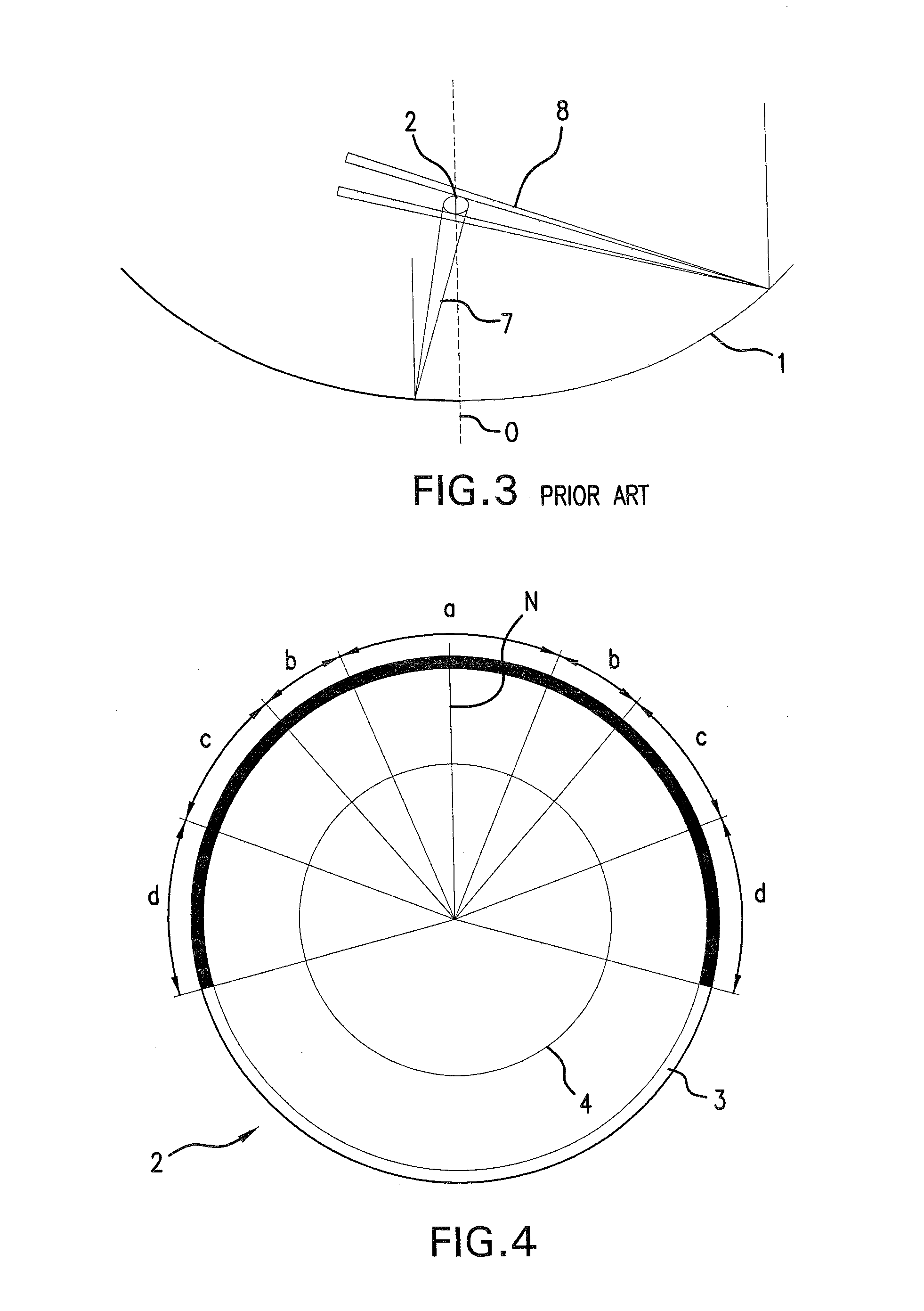
[0037]In FIG. 3 the focussing error due to mirror deformation is illu...


PUM


Abstract

The parabolic trough collector includes a single-axis parabolic mirror (1) and a receiver tube (2) arranged at the focal point (F) of the parabolic mirror (1). The receiver tube (2) includes an absorber tube (4) and an outer tubular glass jacket (3) around it. To compensate for focusing errors in the parabolic collector and thus to reduce associated geometric optical losses, the tubular jacket (3) is provided with structural elements (9a, 9b, 9c, 9d), which focus sunlight reflected from the mirror as well as sunlight that falls directly on the receiver tube from the sun on the absorber tube. The receiver tube is preferably arranged relative to the parabolic mirror, so that its center is displaced from the focal point (F) by a distance equal to half the spacing between the tubular jacket (3) and the absorber tube (4).

Description

BACKGROUND OF THE INVENTION[0001]The present invention relates to a tubular jacket for an absorber tube of a solar energy collector, especially a parabolic trough collector. The invention also relates to a parabolic trough collector for solar energy and a receiver tube for it.[0002]A known parabolic trough collector comprises a single axis parabolic mirror and a receiver tube, which is arranged at the focus of the parabolic mirror. The mirror usually has a width of from 5 to 6 m. The receiver tube comprises a preferably radiation selective inner tube section, which is also called the absorber tube, and an outer tubular jacket made of glass for insulation. Mirror and receiver tube are directed toward the sun, so that the solar radiation always is directed normal to the aperture plane and ideally the radiation falling on the mirror is guided to the receiver tube.[0003]Focusing errors and thus geometrically dependent optical losses occur in parabolic trough collectors due to various fa...

Claims


Application Information

Patent Timeline
IPC IPC(8): F24J2/08F24J2/12F24J2/50F24S20/20F24S23/00F24S23/30F24S23/70F24S23/71F24S23/74
CPCF24J2/062F24J2/07F24J2/14F24J2/08Y02E10/45Y02E10/41F24S20/20F24S23/10F24S23/30F24S23/74Y02E10/40
Inventor KUCKELKORN, THOMAS
Owner SCHOTT AG
Why Eureka
Try Eureka