Optical unit with shake correcting function and photographic optical device

a technology of optical units and shake correction mechanisms, which is applied in the direction of television systems, instruments, printing, etc., can solve the problems of difficult to obtain a stable thrust force, the control of the first the second photographing unit drive mechanism is extremely complicated, and the shake correction mechanism cannot be incorporated into the photographing unit. , to achieve the effect of small power consumption, large torque and efficient interconnection

Active Publication Date: 2012-08-07
SANKYO SEIKI MFG CO LTD
View PDF14 Cites 26 Cited by
  • Summary
  • Abstract
  • Description
  • Claims
  • Application Information

AI Technical Summary

Benefits of technology

[0064]In at least an embodiment of the present invention, it is preferable that outer faces of the first shake correction magnet and the second shake correction magnet are magnetized in different poles in the Z-axis direction, side portions of the first shake correction coil extending in the X-axis direction so as to face respective portions magnetized in different poles of the first shake correction magnet in the Y-axis direction are set to be effective sides, and side portions of the second shake correction coil extending in the Y-axis direction so as to face respective portions magnetized in different poles of the second shake correction magnet in the X-axis direction are set to be effective sides. According to this structure, magnetic fields generated from the first shake correction magnet and the second shake correction magnet are efficiently interlinked with the first shake correction coil and the second shake correction coil. Further, a magnetic driving force acting on the movable module is a force which rocks the movable module in the optical axis direction. Therefore, even when the rocking center of the movable module (position of the pivot part) and a position where a force acting on the movable module are located nearer to each other in the optical axis direction, the magnetic driving force is effectively utilized as a force for rocking the movable module. Accordingly, since a large torque is obtained with a small power consumption, the movable module can be rocked rapidly and surely. As a result, power consumption of a portable apparatus or the like provided with an image-pickup optical device can be reduced and a hand shake can be corrected rapidly and surely.
[0065]In at least an embodiment of the present invention, it is preferable that the first shake correction coil and the second shake correction coil are held on respective faces of a rectangular tube-shaped coil holder which is disposed on an outer side of the movable module. According to this structure, since a structure is attained in which the first shake correction coil and the second shake correction coil are held by a coil holder having a larger strength, positional relationship between the first shake correction coil and the second shake correction coil and the first shake correction magnet and the second shake correction magnet can be obtained with a high degree of accuracy. Therefore, since a large torque is obtained with a small power consumption, the movable module can be rocked rapidly and surely. As a result, power consumption of a portable apparatus or the like provided with an image-pickup optical device can be reduced and a hand shake can be corrected rapidly and surely.
[0066]In at least an embodiment of the present invention, it is preferable that an abutting part is disposed between the fixed body and the movable module, and the movable module and the fixed body are abutted with each other through the abutting part before the movable module is abutted with the shake correction coil and before the shake correction magnet is abutted with the fixed body when the movable module is rocked. According to this structure, even when the shake correction coil and the shake correction magnet are disposed in the vicinity of each other, the shake correction coil and the shake correction magnet can be prevented from being damaged.
[0067]In at least an embodiment of the present invention, it is preferable that an attached module provided with a shutter mechanism is fixed to the fixed body on the object to be photographed side with respect to the movable module. According to this structure, in comparison with a case that the attached module is mounted on the movable module, the weight of the movable module is reduced. Therefore, the movable module can be rapidly and surely rocked and power consumption of a portable apparatus or the like provided with an image-pickup optical device can be reduced.
[0068]In at least an embodiment of the present invention, the movable module is supported by the fixed body so as to be capable of rocking through the pivot part and a movable module drive mechanism for rocking the movable module is provided between the movable module and the fixed body. Therefore, in a case that photographing is performed with a cellular phone with camera or the like on which the optical unit with shake correcting function is mounted, even when a hand shake or the like is occurred, the hand shake or the like is corrected by rocking of the movable module. Accordingly, since the shake correction mechanism is not required to be built into the movable module, even when the shake correction mechanism cannot be provided in the movable module due to a small size of the movable module, a shake is corrected. Further, in at least an embodiment of the present invention, a magnetic force generated by the movable module drive mechanism or an urging force which is generated by the urging means is stable and thus a shake such as a hand shake is corrected with a high degree of accuracy.
[0069]In at least an embodiment of the present invention, although an imaging element flexible wiring member which is electrically connected with the imaging element is drawn out from an end part of the movable module on an opposite side to an object to be photographed side, when a shake such as a hand shake or the like is to be corrected, the movable module is rocked with the side where the imaging element is located with respect to the lens (end part on the opposite side to an object to be photographed side) as a center, deformation of the imaging element flexible wiring member is extremely small. Therefore, the movable module can be rocked rapidly. Further, when the end part of the imaging element side of the movable module is rocked, the elastic deformation of the flexible wiring member is extremely small and thus the shape returning force of the flexible wiring member applied to the movable module is also extremely small. Accordingly, the movable module can be rocked appropriately without receiving effects of the deformation of the flexible wiring member and thus a shake such as a hand shake can be surely corrected. Especially, in at least an embodiment of the present invention, a magnetic drive mechanism is used as an actuator for shake correction. In the case of magnetic driving, although the structure can be simplified and its weight can be reduced, since the movable module is driven in an elastic and a non-contact manner, the movable module is easily affected by an external force. However, in at least an embodiment of the present invention, the deformation of the flexible wiring member is hard to affect as an external force and thus, even when the movable module is structured to be rocked by magnetic driving, the driving is appropriately performed and thus a hand shake correction superior in responsiveness can be performed accurately.

Problems solved by technology

However, in a photographic optical device which is mounted on a small portable apparatus such as a cell phone with camera, a photographing unit is smaller and thus the shake correction mechanism is unable to be incorporated into the photographing unit.
However, like the shake correction mechanism described in Patent Literature 1, in a first photographing unit drive mechanism or in a second photographing unit drive mechanism which is arranged at one side portion with respect to the pivot part, even when a positional relationship between the drive mechanism and the pivot part is slightly displaced, a driving power is varied and thus it is difficult to obtain a stable thrust force.
Therefore, control for the first photographing unit drive mechanism and the second photographing unit drive mechanism are extremely complicated.
In addition, like the shake correction mechanism described in Patent Literature 1, in a structure that a photographing unit drive magnet is provided on a fixed body side and a photographing unit drive coil is provided on a photographing unit side which is a movable body side, since wiring lines for power supply are required to connect with the photographing unit drive coil, the number of wiring lines to the photographing unit is increased and thus a wiring structure is complicated and, on the photographing unit side, it is difficult to increase a winding number of the photographing unit drive coil.
Further, since the photographing unit drive coil whose mass is larger than that of the photographing unit drive magnet is provided on the photographing unit side which is the movable body side, a large force is required to rock the photographing unit and its control is difficult.
Further, like the shake correction mechanism described in Patent Literature 2, in a system in which an end part on an imaging element side of a movable module is rocked, the movable module is unable to be appropriately rocked.
Therefore, the flexible wiring member is also required to be elastically deformed for rocking the end part on the imaging element side of the movable module and thus it is difficult to speedily rock the movable module.
Therefore, an unnecessary force is applied to the end part of the imaging element side of the movable module due to a shape returning force of the flexible wiring member and a magnitude of the shape returning force is varied depending on a deformed state of the flexible wiring member and thus it is difficult that the end part on the imaging element side of the movable module is rocked appropriately.

Method used


Image

  • Optical unit with shake correcting function and photographic optical device
  • Optical unit with shake correcting function and photographic optical device
  • Optical unit with shake correcting function and photographic optical device

Examples


first embodiment

(Entire Structure of Optical Unit with Shake Correcting Function)

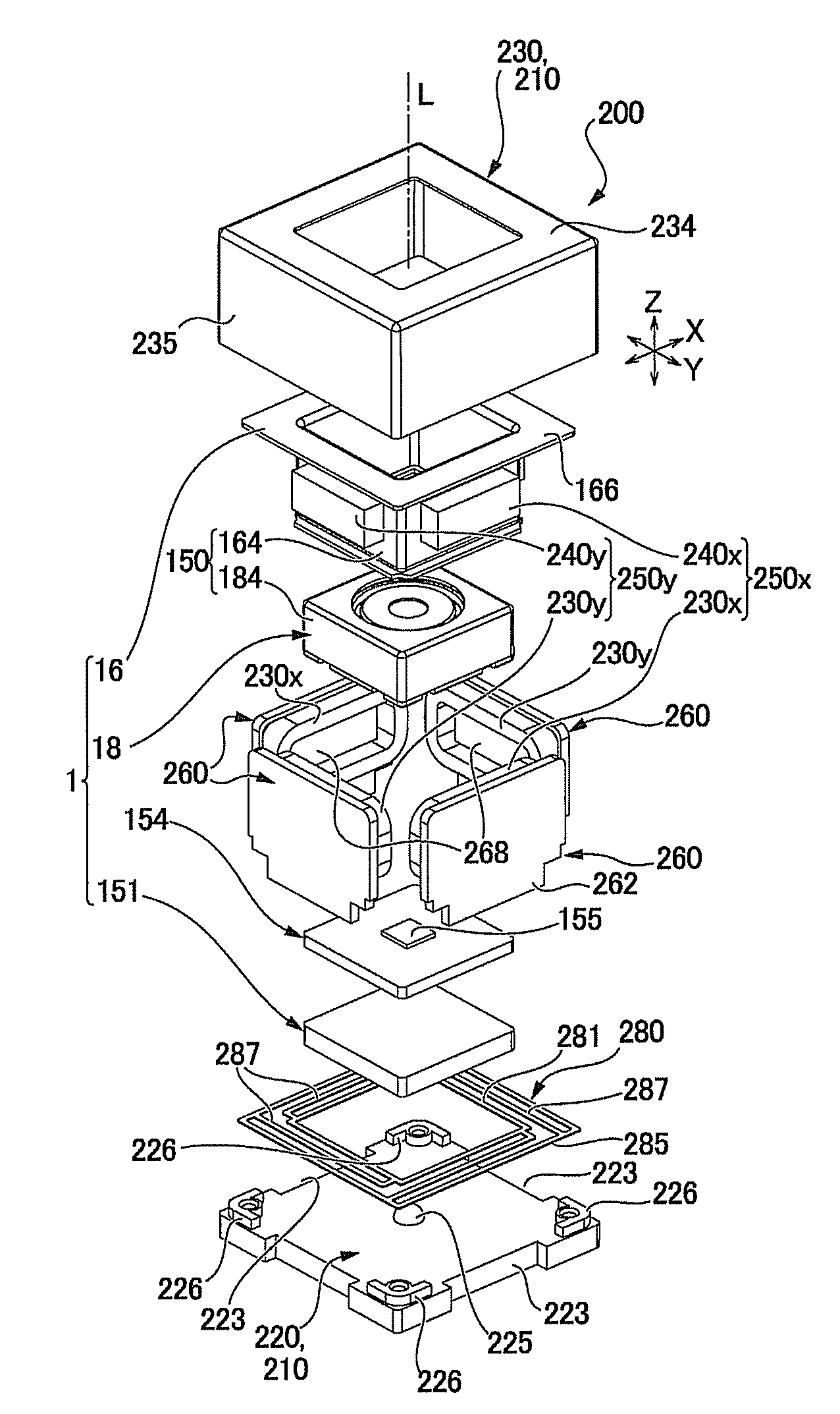
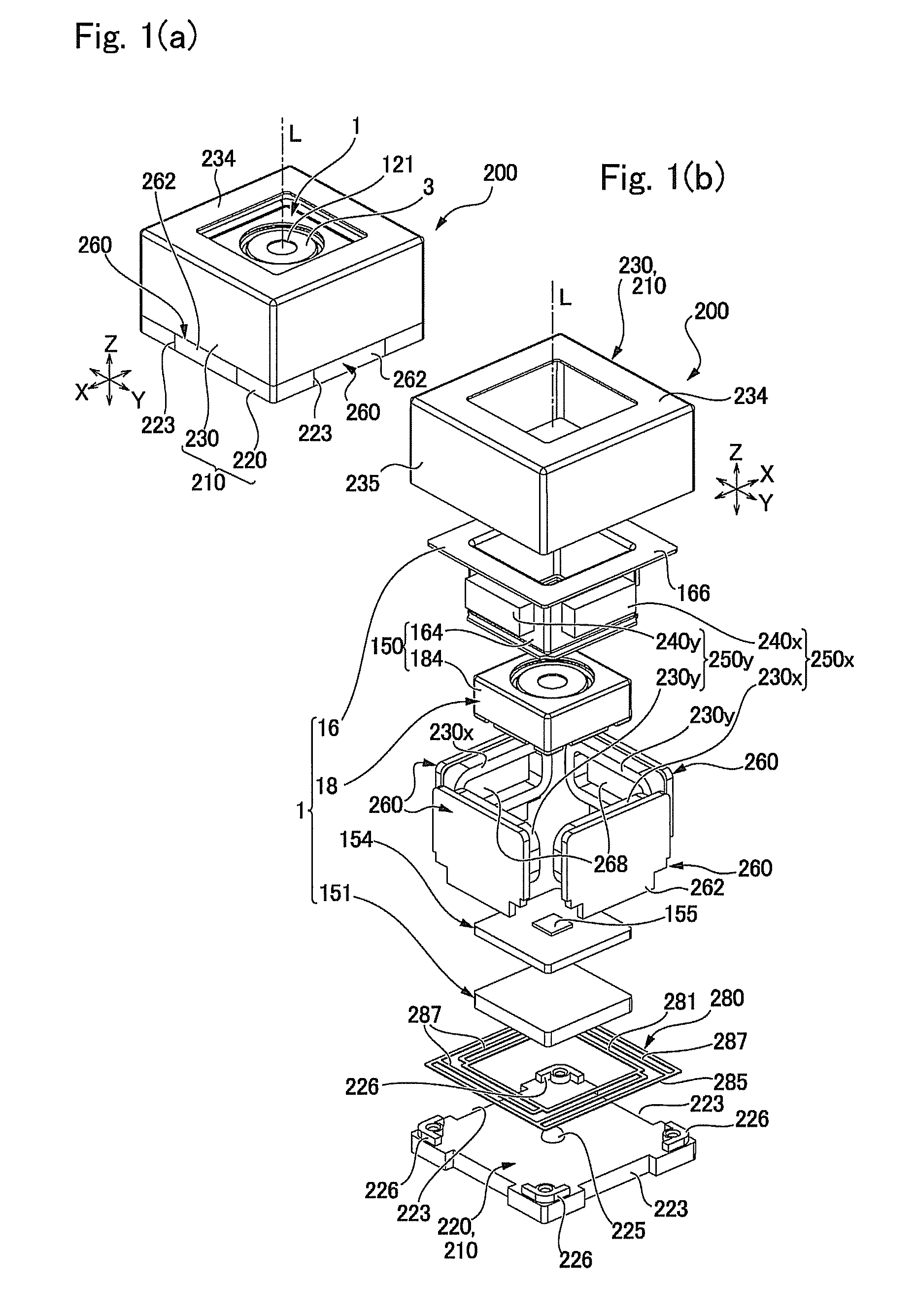
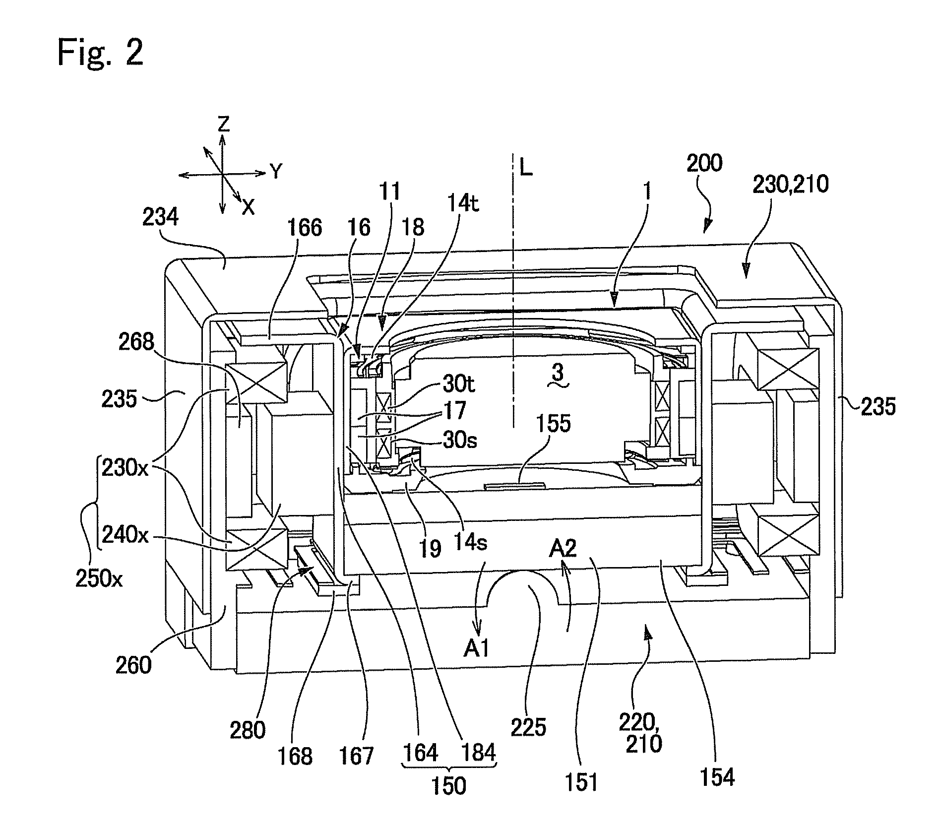
[0092]FIG. 1(a) is an outward appearance view showing an optical unit with shake correcting function in accordance with a first embodiment of the present invention which is viewed from obliquely above on an object to be photographed side, and FIG. 1(b) is its exploded perspective view. FIG. 2 is a longitudinal sectional view showing the optical unit with shake correcting function in accordance with the first embodiment of the present invention which is cut in parallel to the optical axis.

[0093]An optical unit 200 with shake correcting function shown in FIGS. 1(a) and 1(b) and FIG. 2 is a thin type camera which is used in a cell phone with camera and is provided with a substantially rectangular parallelepiped shape as a whole. In this embodiment, the optical unit 200 with shake correcting function includes a base 220 in a rectangular plate shape and a box-shaped fixed cover 230 which is fitted on an upper side of the ba...

second embodiment

[0144]FIG. 5(a) is an explanatory view showing a structure of coil holding members used in an optical unit with shake correcting function in accordance with a second embodiment of the present invention, and FIG. 5(b) is a longitudinal sectional view showing the optical unit with shake correcting function which is cut in parallel to the optical axis. An optical unit with shake correcting function in accordance with the second embodiment is provided with common portions to the optical unit with shake correcting function in accordance with the first embodiment and thus the same reference signs are used in the common portions and their descriptions are omitted.

[0145]In the first embodiment 1, a plate shaped member which is not formed with an opening part is used as the coil holding member 260. However, in the second embodiment, as shown in FIGS. 5(a) and 5(b), the coil holding member 260 is formed of magnetic material and an opening part 265 comprised of a through hole is formed in a po...

third embodiment

[0147]FIG. 6(a) is an outward appearance view showing an optical unit with shake correcting function in accordance with a third embodiment of the present invention which is viewed from obliquely above on an object to be photographed side, and FIG. 6(b) is its exploded perspective view. An optical unit with shake correcting function in accordance with the third embodiment is provided with common portions to the optical unit with shake correcting function in accordance with the first embodiment and thus the same reference signs are used in the common portions and their descriptions are omitted.

[0148]In the first embodiment, as shown in FIGS. 1(a) and 1(b), the fixed cover 230 is provided with the top plate part 234 but, as shown in FIGS. 6(a) and 6(b), a fixed cover 230 which is not provided with the top plate part 234 may be used.

[0149]Further, in the first embodiment, as shown in FIGS. 1(a) and 1(b), the yoke 16 is provided with the flange part 166 which is stretched to the outer pe...


PUM


Abstract

Provided is a photographing optical device, which is able to reliably correct an unintentional movement by hand of a user by improving the constitution of a camera unit driving mechanism for correcting the deflection of a camera unit. In order that a camera unit is made to be rocked to correct the unintentional movement, a photographing optical device includes a first camera unit drive mechanism and a second camera unit drive mechanism, which are so disposed at two side portions sandwiching a pivot portion therebetween as to make a pair. In these camera unit drive mechanisms, camera unit driving magnets are held on the side of the camera unit as a movable body side, and camera unit driving coils are held on the side of a stationary body. The camera unit is pushed toward the pivot portion by a gimbal spring.

Description

CROSS REFERENCE TO RELATED APPLICATIONS[0001]This is a Continuation Application of International Application No. PCT / JP2009 / 001912, filed on 27 Apr. 2009, the disclosure of which is incorporated herein by reference in its entirety. International Application No. PCT / JP2009 / 001912 claims priority to Japanese Patent Applications No. 2008-118579, filed Apr. 30, 2008; 2008-147187, filed Jun. 4, 2008; and 2008-334723, filed Dec. 26, 2008; priority to each of which is claimed herein and the contents of each of which are incorporated herein by reference.TECHNICAL FIELD[0002]The present invention relates to an optical unit with shake correcting function which is mounted on a cell phone with camera or the like, and a photographic optical device into which a shake correcting function is incorporated.BACKGROUND[0003]A photographic optical device which is mounted on a portable apparatus is provided with a movable body including a lens, a lens drive mechanism for magnetically driving the movable ...

Claims


Application Information

Patent Timeline
Patent Type & Authority Patents(United States)
IPC IPC(8): G03B17/00H04N5/228G02B7/04G03B5/00
CPCG02B7/022G02B7/08G02B27/646G03B17/00H04N5/2253H04N5/2254H04N5/2257H04N5/23248H04N5/23287H04N23/54H04N23/57H04N23/55H04N23/60H04N23/68H04N23/687
Inventor TSURUTA, TOSHIFUMIMIYAZAKI, KIYOSHITAKEDA, TADASHIISHIHARA, HISAHIROYANAGISAWA, KATSUSHIGEKARASAWA, TOSHIYUKITAKEI, YUICHINAGATA, AKIHIROMINAMISAWA, SHINJI
Owner SANKYO SEIKI MFG CO LTD
Why Eureka
Try Eureka