Eureka AIR delivers breakthrough ideas for toughest innovation challenges, trusted by R&D personnel around the world.

Electric motor design for in hub motors

a technology of hub motors and electric motors, which is applied in the direction of mechanical energy handling, magnetic circuit rotating parts, shape/form/construction, etc., can solve the problems of high production cost, production errors, and difficult cutting of inner peripheral grooves and automatic inserting of permanent magnets, and achieve low production cost, low production cost, and easy production

Active Publication Date: 2009-09-01
IND TECH RES INST
View PDF41 Cites 17 Cited by
  • Summary
  • Abstract
  • Description
  • Claims
  • Application Information

AI Technical Summary

Benefits of technology

[0006]It is the object of the present invention to provide an electric motor which is easy to produce and which is manufactured at low cost and with little waste material.
[0007]The electric motor of the present invention has a stator and a rotor, both of which have plates that are divided into several sectors. The sectors are made by punching at high precision and are automatically assembled, facilitating automatic inserting of permanent magnets.

Problems solved by technology

Since cutting of the inner peripheral grooves and automatic inserting of the permanent magnets is difficult, the permanent magnets are usually glued to an inner periphery of the rotor body.
This method, however, is expensive and often results in errors of production.
However, since the rotor plates have relatively large diameters, large punching machines are required, and punching produces large quantities of waste material, leading to high cost of production.

Method used


Image

  • Electric motor design for in hub motors
  • Electric motor design for in hub motors
  • Electric motor design for in hub motors

Examples


Embodiment Construction

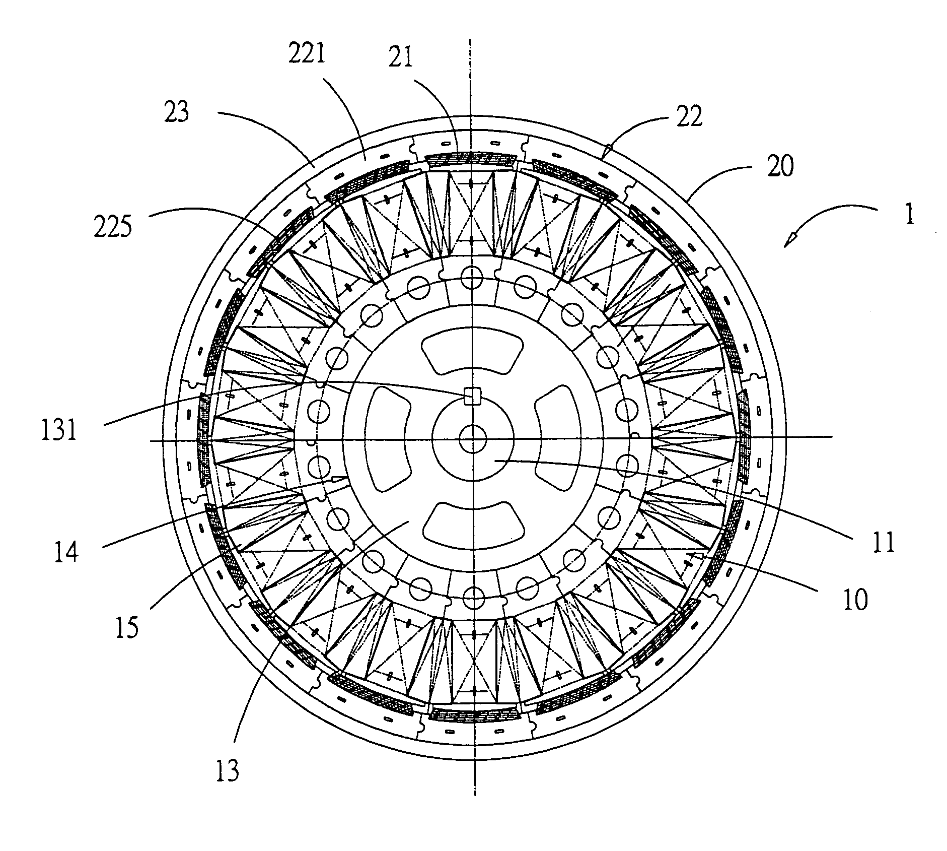
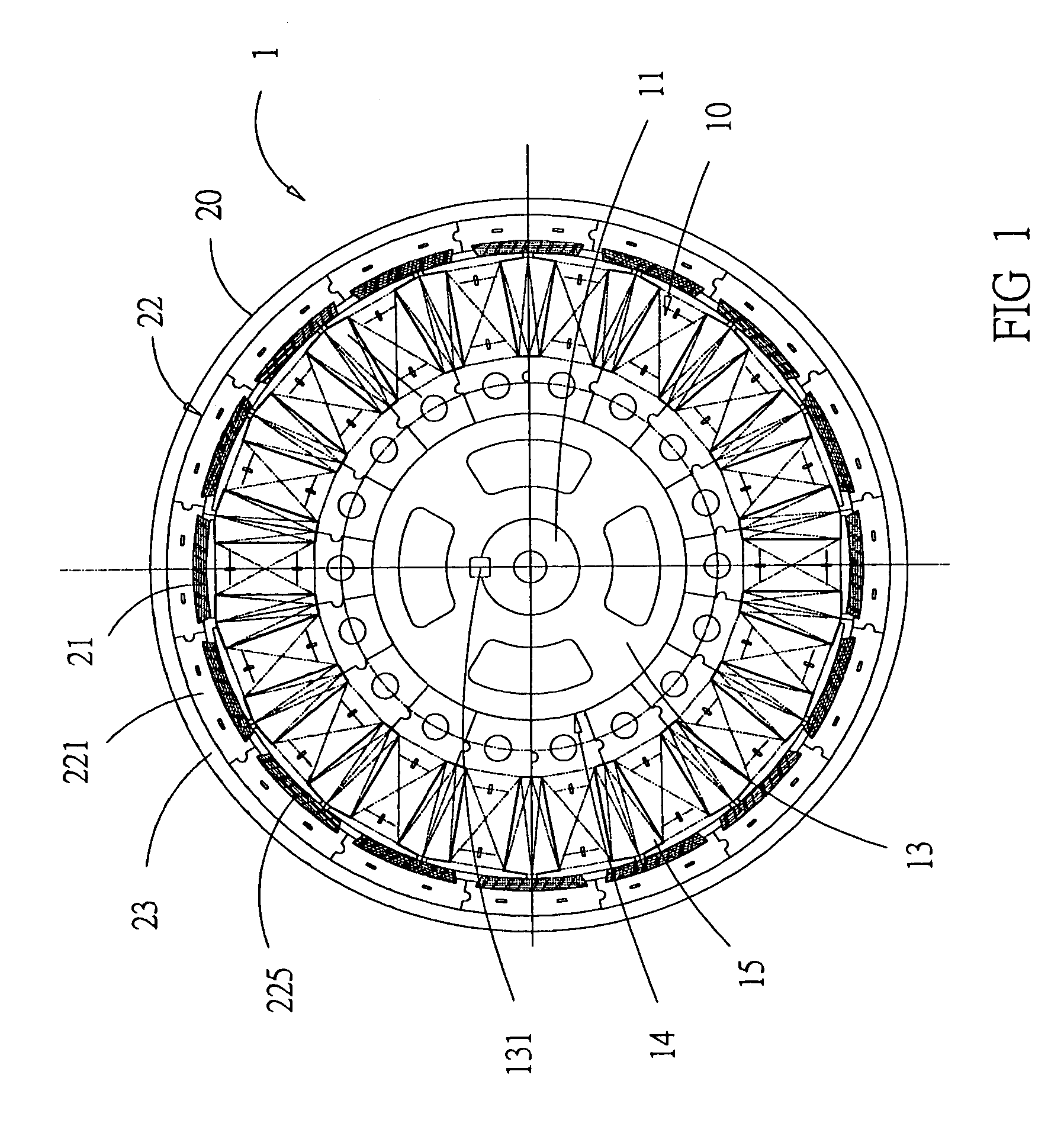
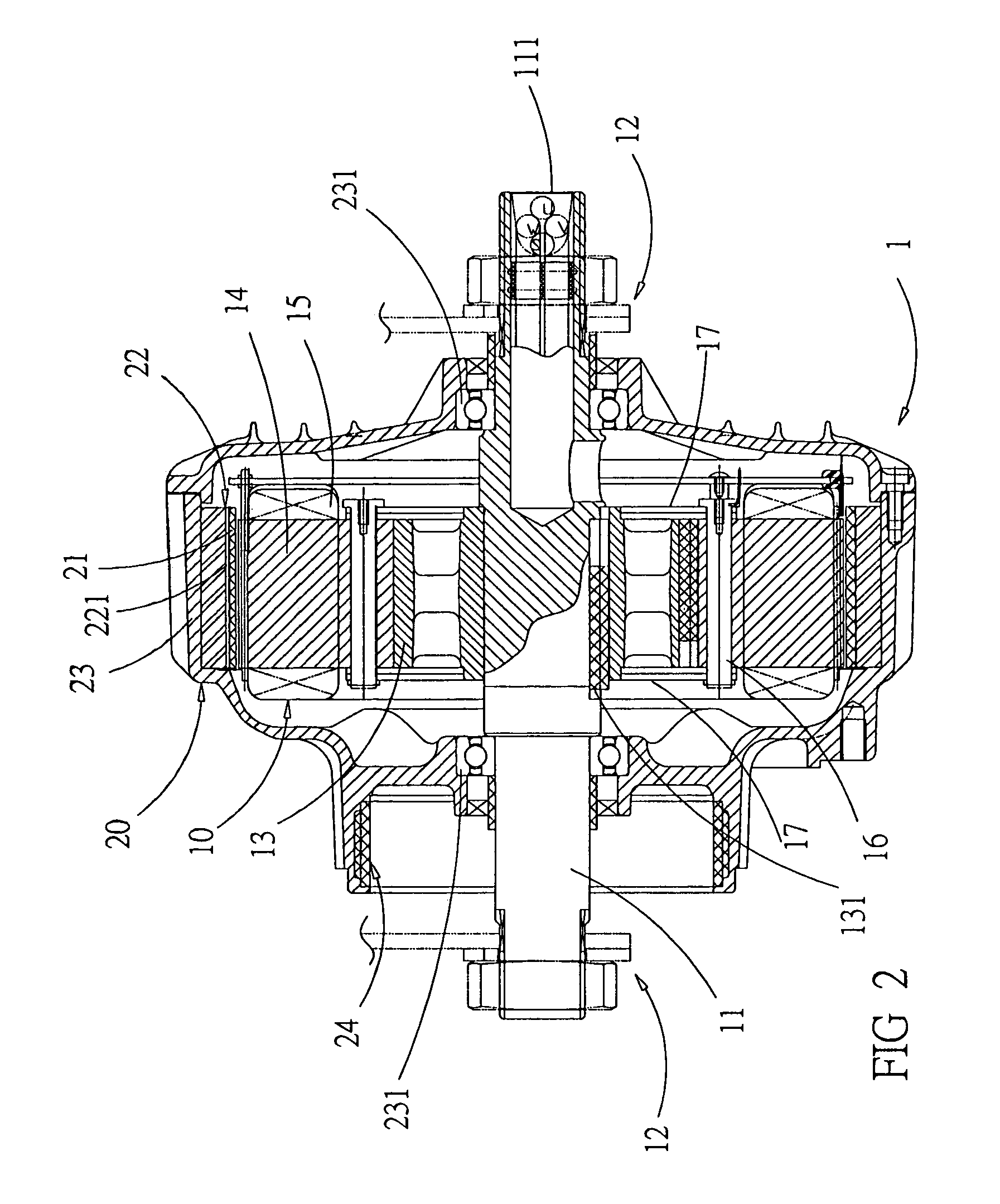
[0019]As shown in FIGS. 1 and 2, the electric motor of the present invention has a rotor that surrounds a stator, working as a motor or as an electricity generator. The following explanation takes a motor used in a hub of an electric vehicle or in a washing machine as an example. The electric motor 1 of the present invention comprises: A stator assembly 10, having electric coils 15; and a rotor assembly 20, having permanent magnets 21. The rotor assembly 20 is made of a plurality of rotor plates stacked on top of each other, and the stator assembly 10 is made of a plurality of stator plates stacked on top of each other. The rotor plates and the stator plates are each divided into a plurality of sectors, resulting in easy manufacturing at low cost. In the following, a detailed explanation is given.

[0020]The stator assembly 10 has a stator axle 11 with two ends that are fastened to a stator frame 12. A stator plate sector holder 13 is by a bolt 131 fixed to the stator axle 11, and is ...


PUM


Abstract

An electric motor design for hub motors comprises a stator assembly, having an axle, a stator plate sector holder, fixed on the axle, at least one stator sector assembly, mounted on the stator plate holder, and electric coils, would around the plates of the stator plate assembly; and a rotor assembly, having a casing, a rotor magnet retainer assembly, placed inside of the casing, and at least one permanent magnet, mounted on plates of the rotor magnet retainer assembly; wherein the stator sector assembly and / or the rotor magnet retainer assembly have plates which are stacked on top of each other and which are each divided into at least two sectors, saving production cost.

Description

BACKGROUND OF THE INVENTION[0001]1. Field of the Invention[0002]The present invention relates to an electric motor, particularly to an electric hub motor in which rotor and stator plates divided in several sections are substituted for a conventional rotor and stator plates in single pieces. Thereby cost of molding and waste material are greatly reduced and unused material of other processes is usable, resulting in a significant cost advantage.[0003]2. Description of Related Art[0004]In conventional art, brushless peripheral-rotor motors, in which rotors are placed outside stators, are widely used in hubs of electric vehicles and washing machines. Motors of this type have inner stators with a plurality of electric coils connected with power. During operation as an electric generator, a rotating external magnetic field results in the generation of electric current. In each motor of this type, the rotor has a larger diameter than the stator and is provided with a plurality of permanent...

Claims


Application Information

Patent Timeline
Patent Type & Authority Patents(United States)
IPC IPC(8): H02K1/18H02K1/27
CPCH02K1/148H02K21/22H02K1/2786H02K1/2791
Inventor LU, CHUN-HSIENGU, HUAN-LUNGHSU, CHI-TANG
Owner IND TECH RES INST
Why Eureka
Eureka Blog
Learn More