Syringe pump

a technology of syringe and syringe, which is applied in the direction of piston pumps, laboratory glassware, instruments, etc., can solve the problems of unreliable control, poor use of valuable labor time, and no direct control of reaction mixture, so as to reduce the amount of human monitoring and facilitate the dispense of reagents

Inactive Publication Date: 2007-12-25
HODSON STEVE J
View PDF21 Cites 21 Cited by
  • Summary
  • Abstract
  • Description
  • Claims
  • Application Information

AI Technical Summary

Benefits of technology

[0009]Accordingly, one objective of the present invention is to provide a device that delivers reagents to a chemical reaction mixture in such a way as to substantially decrease the amount of human monitoring needed during the addition rate. Another objective is to control the addition rate of reagent over time according to how a particular reaction is proceeding. Yet another objective is to provide a small, hand-held, automated syringe pump that can be easily programmed to dispense reagent from a syringe. A further objective is to provide a device capable of sensing physical properties of a chemical reaction and control that reaction's progress automatically.
[0010]To this end, the syringe pump of the present invention provides automated control of the addition of reagent into a reaction mixture. In addition, the invention enables automated changes in the dispensing rate of reagent according to changes in temperature and ion content (i.e. hydrogen, chloride, chlorate, perchlorate, fluoride, sodium, calcium, and iron ions, as well as the oxygen content in the water) as the reaction progresses. Further, the device allows the user to program the automated delivery of either very small or very large amounts of reagent over time, and permits the optional addition of a check-valve assembly to the syringe, so that multiple syringe loads may be delivered to the reaction mixture over time.
[0012]The pump preferably has an external housing that includes a head, a body, and a base, with the motor and power for the pump located in the head, the drive shaft and drive block located in the body, and the barrel clamp housed in the base. The drive shaft is connected at one end to the motor, and the other end of the drive shaft is free to rotate in a journal bearing located on the external housing for the base. In accordance with one aspect of the invention, the device is relatively small, hand-held, inexpensive, and requires significantly less set-up time than other prior art pumps.
[0013]The pump may be set up such that no transfer lines between the syringe and the reaction mixture are present, which permits the performance of chemical reactions in an inert atmosphere. It also provides highly accurate delivery of reagent into the reaction mixture and requires no monitoring during the addition phase. In addition, the apparatus is small enough to be used under a laboratory reaction hood and without user interaction, thus allowing the reaction to proceed in a safe environment while leaving the users hands free to perform other activities.
[0014]In accordance with another aspect of the invention, the device incorporates input jacks for receiving plug-in probes. The probes can have a their sensing end placed into the reaction mixture, and the plug-in end is plugged into the jacks located on the pump, thereby allowing the logic control circuit to measure physical properties of the mixture as the reaction proceeds. The information received from the reaction mixture allows the logic control circuit to change the dispensing rate of reagent during the addition phase to adapt to changes in the reaction milieu, thus providing a high degree of reaction mixture control.
[0015]The syringe pump of the present invention can employ commonly available disposable plastic syringes to transfer and deliver a single portion of liquid of about 1 ml to about 50 ml volume, and over any desired time from about 1 to about 99 minutes. Thus the reagent is dispensed at a rate of ml / min, ml / hour, cm / sec, etc. The disposable plastic syringe can be easily mounted on the pump, and, once loaded into the syringe pump, can also be connected to a check valve for delivering multiple syringe volumes (i.e. in the range of 1 liter of total volume) to the reaction mixture over time.

Problems solved by technology

While this manual method may afford good control of the addition rate of the reagent, it requires “hands-on” syringe operation to inject small portions of the reagent over time, resulting in poor use of valuable labor time.
Addition funnels have long been used to control addition of chemical reagent to a reaction mixture, but they give unreliable control, require “hands-on” adjustment during the addition phase, and offer no direct control of the reaction mixture.
This method requires significant monitoring by the chemist and gives poor control of the addition rate.
Liquid transfer pumps (i.e. piston pumps) are sometimes used in this process, but these piston pumps are generally unreliable, being prone to leakage and seizure during operation.
Most available prior art programmable syringe pump devices are large (requiring up to a square ft. of bench top space), expensive, and require significant set-up time.
In addition, their large size usually requires them to have a transfer line connecting the syringe to the reaction mixture, creating the problem of reagent material being trapped in the transfer lines.
The company J-Kem® sells a multiple component system consisting of three separate devices that will control a syringe based on temperature or pH, however this system is bulky, requires electrical cords, and is not portable.
No prior art syringe pump is available as a single, hand-held device capable of monitoring physical properties of the reaction mixture such as temperature and / or ion content thereof, and then altering the programmed addition rate of the reagent to the reaction mixture according to these physical properties.

Method used


Image

  • Syringe pump
  • Syringe pump
  • Syringe pump

Examples


Embodiment Construction

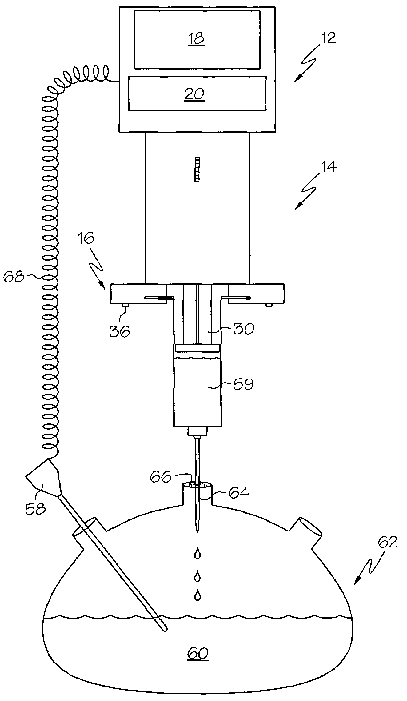
[0027]For purposes of this invention, the term “pH” is defined as follows: a measure of acidity and alkalinity of a solution that is a number on a scale on which a value of 7 represents neutrality and lower numbers indicate increasing acidity and higher numbers increasing alkalinity and on which each unit of change represents a tenfold change in acidity or alkalinity and that is the negative logarithm of the effective hydrogen-ion concentration or hydrogen-ion activity in gram equivalents per liter of the solution.

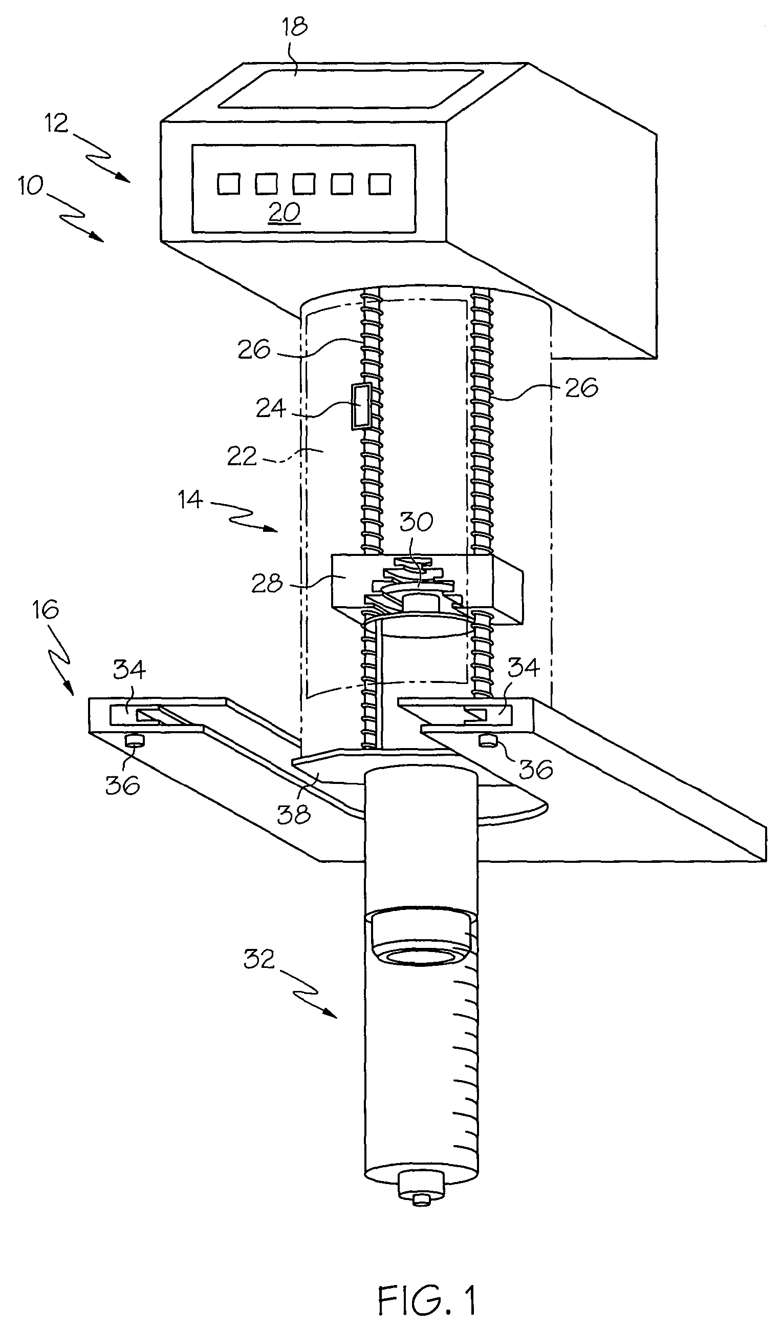
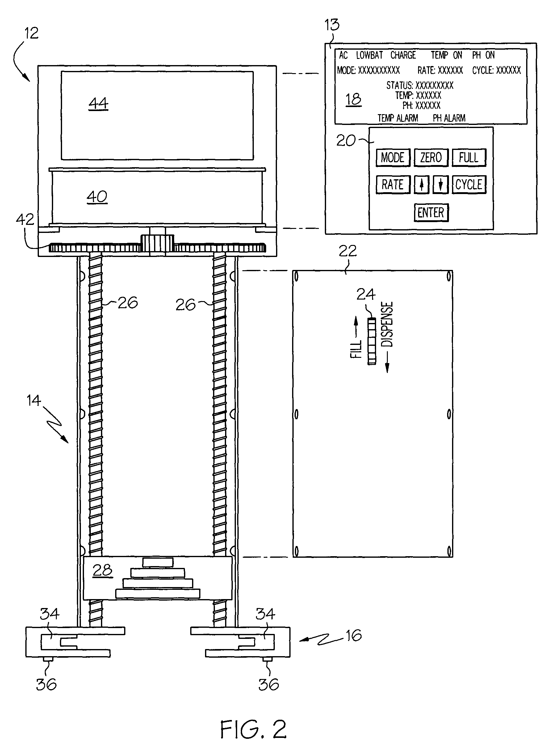
[0028]Referring now to FIG. 1 of the drawings, the syringe pump 10 includes a head 12, a body 14 (shown in phantom) and a base 16. On the outer housing of the head 10 there is display 18, preferably in the form of an LCD display panel, and a keypad 20 having control buttons. On the outer housing of the body 14 there is a body cover 22 (in phantom) with a manual control switch 24. Inside the housing of the body 14 are drive shafts 26 and a drive block 28 which secures a plu...


PUM


Abstract

The invention is directed to a syringe pump for the controlled addition of reagents to a chemical reaction. The pump has a reduced size for use as a cordless, hand-held laboratory device, and includes a driving mechanism for moving the plunger of a syringe along the syringe barrel, a means for sensing a physical property of the reaction mixture, and a logic control circuit. The driving mechanism includes a motor, a drive shaft, a drive block, and a sliding barrel clamp. The logic control circuit is programmable and controls the syringe pump based on predetermined parameters. The syringe pump adapts the delivery rate of reagent according to changes in physical properties of the reaction mixture such as pH and / or temperature, thus providing a high degree of automated control over a chemical reaction.

Description

BACKGROUND OF THE INVENTION [0001]I. Field of the Invention[0002]The present invention relates generally to syringe pumps, and in particular to a programmable, battery-charged syringe pump for the controlled addition of reagents to a chemical reaction, which can adapt the rate of addition of reagent according to changes in physical properties of the reaction mixture such as reaction temperature and pH content.[0003]II. Description of the Prior Art[0004]In small-scale chemical reactions (e.g. laboratory research), the controlled addition of reagents to a chemical reaction is often accomplished by use of disposable plastic syringes. A scientist may choose to fill a disposable syringe with the desired reagent and then manually control the rate of addition of the reagent into a reaction mixture. While this manual method may afford good control of the addition rate of the reagent, it requires “hands-on” syringe operation to inject small portions of the reagent over time, resulting in poo...

Claims


Application Information

Patent Timeline
Patent Type & Authority Patents(United States)
IPC IPC(8): B01L3/02F04B9/02
CPCB01L3/0227F04B9/02B01L2200/143B01L2200/147Y10T436/2575B01L2300/0627B01L2300/027
Inventor HODSON, STEVE J.
Owner HODSON STEVE J
Why Eureka
Try Eureka