Apparatus and method for displaying operating characteristics on status indicators

a status indicator and display device technology, applied in the direction of identification means, instruments, anti-theft devices, etc., can solve the problems of inability to immediately observe the speed of the fan motor by visual feedback, and the mechanical inertia of the fan motor is so grea

Active Publication Date: 2007-12-25
LUTRON TECH CO LLC
View PDF15 Cites 54 Cited by
  • Summary
  • Abstract
  • Description
  • Claims
  • Application Information

AI Technical Summary

Problems solved by technology

However, when a fan motor is controlled by a load control device, the mechanical inertia of the fan motor is so great that an immediate visual feedback of the speed of the fan motor by observation of the fan is not possible.

Method used


Image

  • Apparatus and method for displaying operating characteristics on status indicators
  • Apparatus and method for displaying operating characteristics on status indicators
  • Apparatus and method for displaying operating characteristics on status indicators

Examples


first embodiment

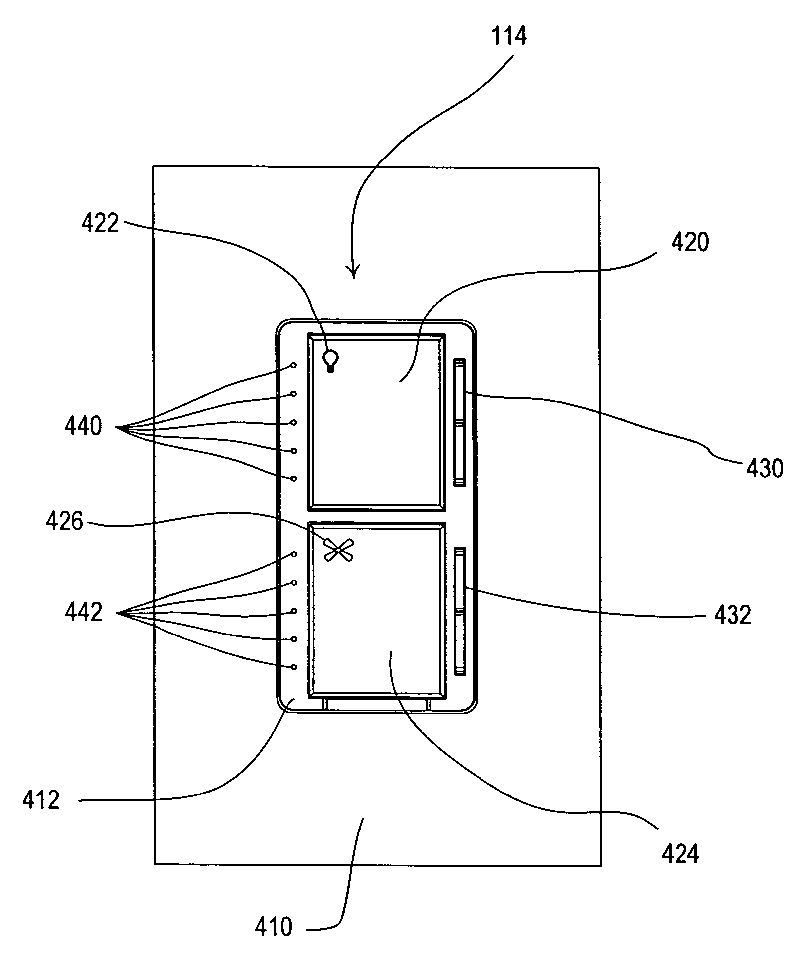
[0029]FIG. 5 demonstrates a first embodiment for illuminating the status indicators 442 to indicate M fan speeds on N status indicators, where M is greater than N. In the case of FIG. 5, the number N of status indicators 442 is five, while the number M of discrete fan speeds is nine. The status indicators 442 are arranged in a linear array with each individual status indicator, X, having a value of 1≦X≦N. A non-illuminated status indicator 510 is designated by a white circle and a fully illuminated status indicator 520 is designated by a black circle. Each of the different fan speeds, L, where 1≦L≦M is represented by a unique combination of illuminated status indicators. The off speed (L=0), i.e., when the fan motor is not moving, is not considered one of the M fan speeds since none of the status indicators are illuminated for this speed as shown in FIG. 5(a).

[0030]The configurations of status indicators shown in FIG. 5 are preferably ordered such that as greater discrete fan speeds...

second embodiment

[0034]FIG. 6 demonstrates a second embodiment for illuminating the status indicators 442 to indicate M fan speeds on N status indicators, where M is greater than N. In FIG. 6, the number N of status indicators 442 is five, while the number M of discrete fan speeds is seven. A dimly illuminated status indicator 530 is designated by a crosshatched circle. The dimly illuminated status indicator 530 is illuminated at an intensity level that is less than the intensity level of the fully illuminated status indicator 520, but substantially different in intensity, such that the user of the load control device is able to distinguish the difference in the intensities of the dimly illuminated status indicator and the fully illuminated status indicator. Once again, the off speed (L=0), i.e., when the fan motor is not moving, is not considered one of the M fan speeds since no status indicators are illuminated for this speed as shown in FIG. 6(a).

[0035]The method of FIG. 6 attempts to illuminate ...

third embodiment

[0040]FIG. 7 shows a third embodiment for illuminating the status indicators 442 to indicate M fan speeds on N status indicators, where M is greater than N. In FIG. 7, the number N of status indicators 442 is five, while the number M of discrete fan speeds is eight. Once again, the off speed (L=0), i.e., when the fan motor is not moving, is not considered part of the M fan speeds since no status indicators are illuminated for this speed as shown in FIG. 7(a).

[0041]With the embodiment of FIG. 7, multiple fan speeds (for example, two speeds in FIG. 7) are indicated by the same configurations of status indicators. For example, the second fan speed (L=2) and third fan speed (L=3) above the zero fan speed are represented by the same status indicator configuration as shown in FIGS. 7(c) and 7(d), i.e., the second status indicator (X=2) from the bottom of the linear array is illuminated. For the configurations of status indicators at the high-end (L=8) or low-end (L=1) of the fan speed ran...


PUM


Abstract

A user interface for a load control device allows a user to control an operating characteristic of a load to a plurality of discrete levels. The user interface comprises an adjustment member for allowing the user to select one of the discrete levels and a linear array of status indicators for displaying the discrete level. The number of discrete levels is greater than the number of status indicators. According to a first embodiment of the present invention, either one status indicator or two consecutive status indicators are illuminated to indicate the presently selected discrete level. According to a second embodiment, a fully illuminated status indicator is surrounded by two dimly illuminated status indicators to indicate the presently selected discrete level. According to a third embodiment, a single status indicator may be illuminated to indicate one or more of the discrete levels.

Description

RELATED APPLICATIONS[0001]This application is related to Provisional Application No. 60 / 687,828, filed Jun. 6, 2005, entitled METHOD AND APPARATUS FOR QUIET VARIABLE MOTOR SPEED CONTROL, which is assigned to the assignee of the present application, the entire disclosure of which is hereby incorporated by reference. The above application will herein be referred to as the “Motor Speed Control” application.[0002]This application is related to Provisional Application No. 60 / 687,691, filed Jun. 6, 2005, entitled POWER SUPPLY FOR A LOAD CONTROL DEVICE, which is assigned to the assignee of the present application, the entire disclosure of which is hereby incorporated by reference. The above application will herein be referred to as the “Power Supply” application.[0003]This application is related to Provisional Application No. 60 / 687,689, filed Jun. 6, 2005, entitled SYSTEM FOR CONTROL OF LIGHTS AND MOTORS, which is assigned to the assignee of the present application, the entire disclosure ...

Claims


Application Information

Patent Timeline
Patent Type & Authority Patents(United States)
IPC IPC(8): B60R25/10
CPCG09F9/302G09F9/33H05B33/0803H05B39/04H05B37/0272H05B37/029H05B33/0842H05B47/155H05B47/00
Inventor LEHMER, MATTHEW J.BORING, NATHANDOBBINS, AARON
Owner LUTRON TECH CO LLC
Why Eureka
Try Eureka