
Multiplier circuit

a multiplication circuit and circuit technology, applied in the field of multiplication circuits, can solve the problems of large, complex, expensive, slow and time-consuming to lay out, and the structure of the wallace tree adder array b> is not suitable for use in conjunction with the large number of partial products typically generated when multiplying large binary numbers

Active Publication Date: 2007-12-25
VALTRUS INNOVATIONS LTD
View PDF30 Cites 57 Cited by
  • Summary
  • Abstract
  • Description
  • Claims
  • Application Information

AI Technical Summary

Benefits of technology

This approach allows for faster calculation times proportional to the logarithm of the number of bits while simplifying the layout process, reducing the effort and time required for implementing the circuitry, thus addressing the limitations of conventional Wallace tree structures.

Problems solved by technology

In particular, the movement toward processors with 64-bit architectures poses particular challenges for designers of multiplier circuits, since the rote application of old methodologies to such architectures may produce multiplier circuit designs that are large, complex, costly, slow, and time-consuming to lay out.
Although the layout and operation of the linear adder array 502 are straightforward, the size and calculation time of the linear adder array 502 increases linearly with the number of partial products, thereby making it poorly-suited to use in conjunction with the large number of partial products typically generated when multiplying large binary numbers.
The structure of the Wallace tree adder array 540 is complex, however, making it difficult to lay out schematics for circuitry implementing a conventional Wallace tree quickly, easily, and efficiently.
As a result of the Wallace tree's complex structure, circuits implementing Wallace trees tend to include long wiring paths.
The signal propagation delays incurred on such paths can be significant enough to significantly mitigate or even negate the theoretical speed benefits of Wallace trees.

Method used


Image

  • Multiplier circuit
  • Multiplier circuit
  • Multiplier circuit

Examples


Embodiment Construction

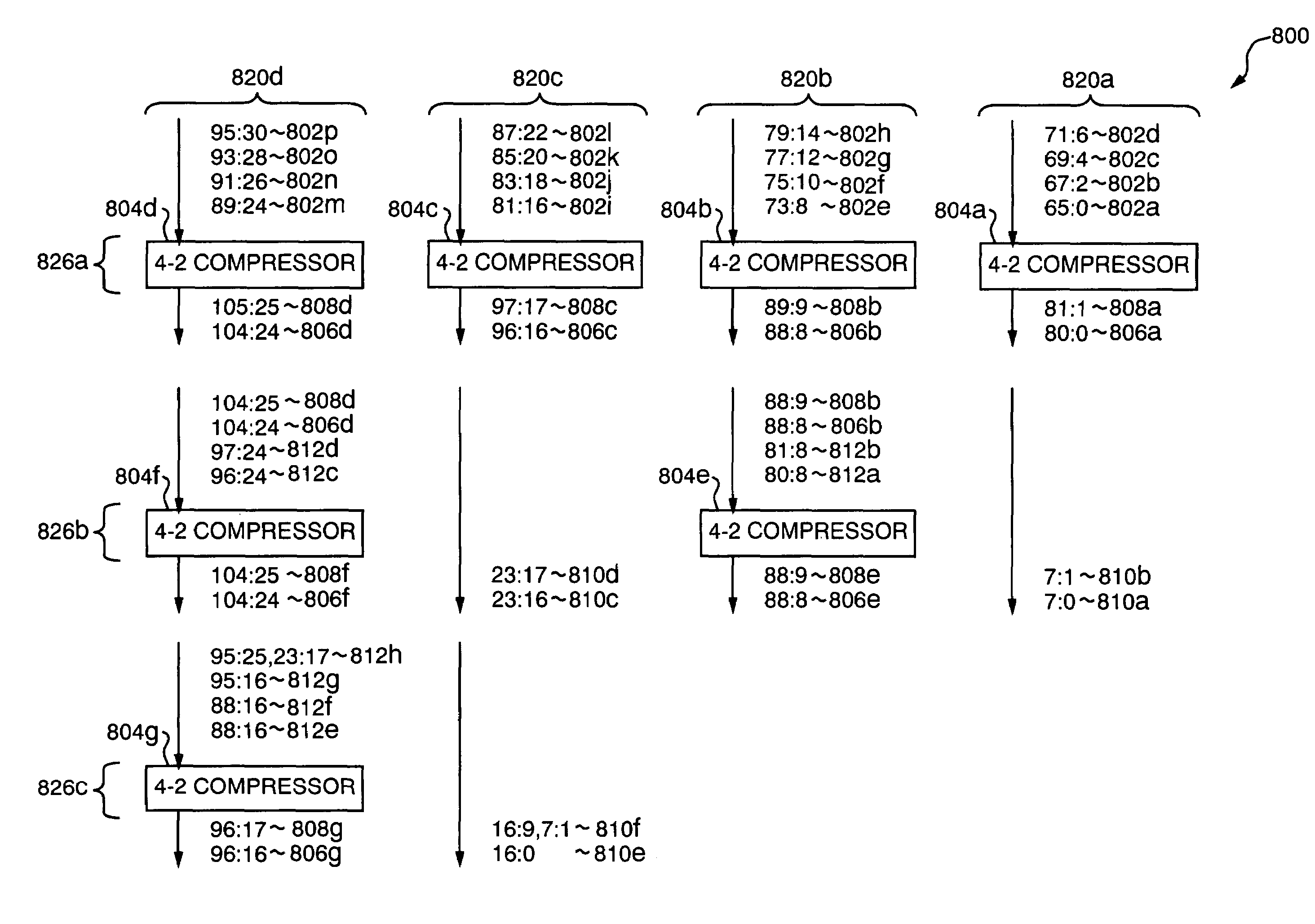
[0043]Before describing particular embodiments of the present invention, additional features of conventional Wallace trees will be described in more detail. Referring to FIG. 6, a diagram is shown of a system 600 in which a conventional Wallace tree structure is employed to sum 16 partial products 602a–p, each of which is 66 bits wide. Such products 602a–p may, for example, be one of two sets of partial products generated when a 64-bit multiplicand is multiplied by a 64-bit multiplier using radix-4 Booth encoding. As stated above, the partial products 602a–p are 66 bits wide rather than 64 bits wide because they are encoded using Booth encoding and sign extended one bit further to simplify the execution of signed and unsigned multiplication using the same multiplier circuit.

[0044]FIG. 6 illustrates each of the partial products 602a–p and other numerical values using the notation x:y, which specifies a binary number having a most significant bit at column x and a least significant bi...


PUM


Abstract

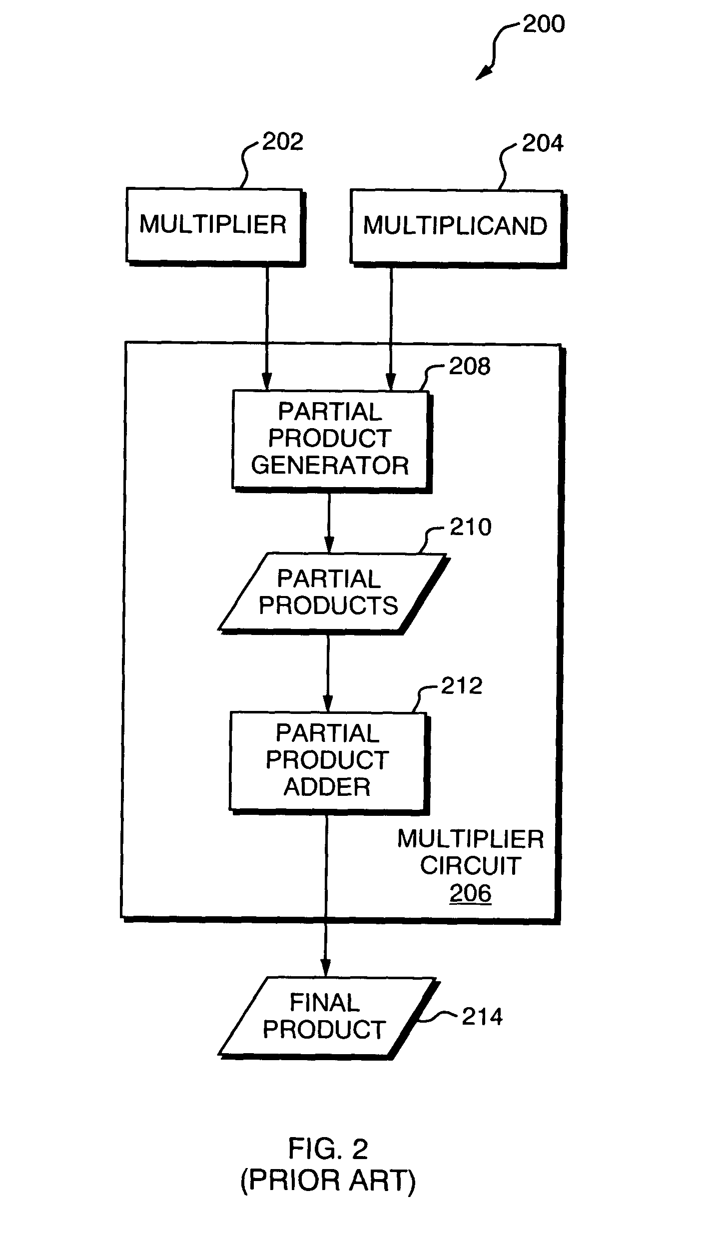
A multiplier circuit is disclosed for multiplying a multiplicand by a multiplier. The multiplier circuit includes a partial product generator and a partial product adder. The partial product generator includes a first input to receive a multiplicand; a second input to receive a multiplier; partial product generation means for producing a plurality of partial products based on the multiplicand and the multiplier; and an output coupled to the partial product generation means to provide the plurality of partial products. The partial product adder includes an input coupled to the output of the partial product generator; a plurality of adders to add the plurality of partial products to produce a final product, the plurality of adders comprising a plurality of compressors having substantially the same width; and an output coupled to the plurality of adders to provide the final product.

Description

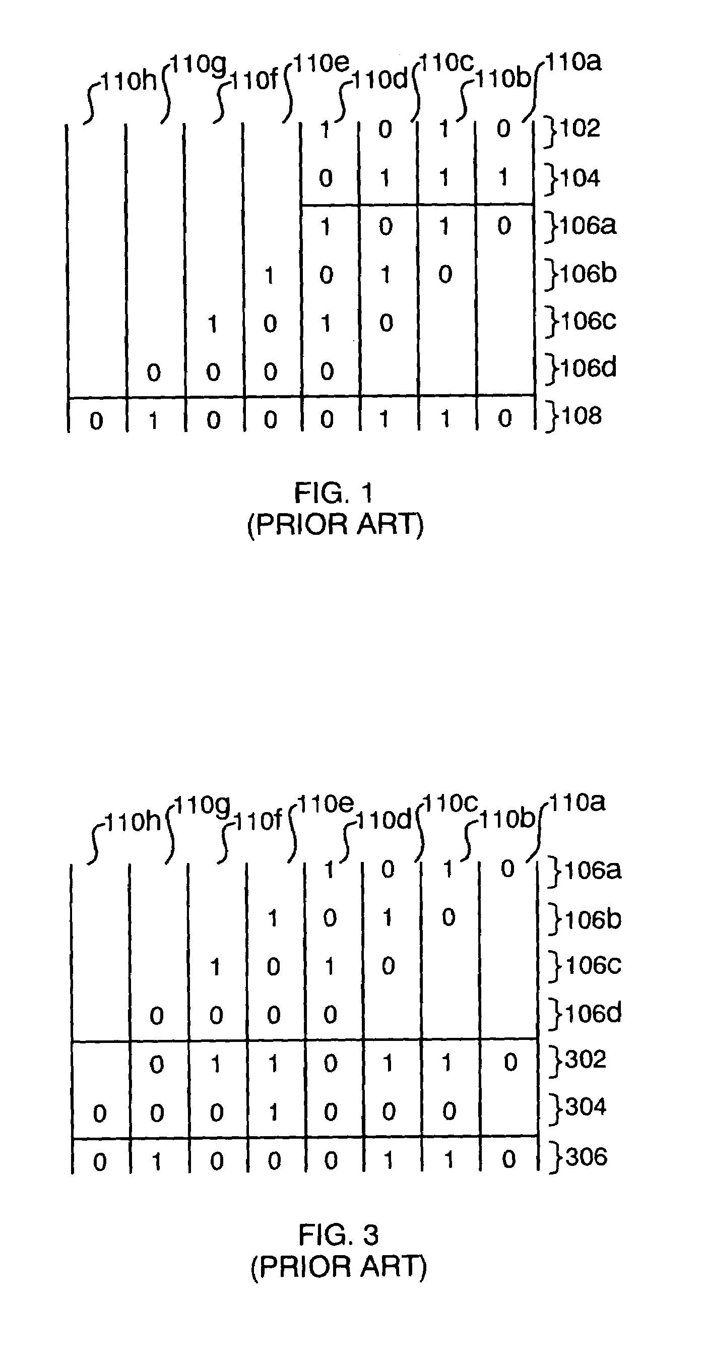
BACKGROUND[0001]1. Field of the Invention[0002]The present invention relates to multiplier circuits for use in computer systems.[0003]2. Related Art[0004]Modern microprocessors and other integrated circuits typically include dedicated multiplier circuits for multiplying binary numbers. It is desirable that multiplier circuits be easy to design, capable of fitting in a small area, capable of performing multiplication quickly, and inexpensive to manufacture. Circuit designers continue to be challenged by these design goals as the need continues to increase for processors that are ever smaller, faster, and inexpensive. In particular, the movement toward processors with 64-bit architectures poses particular challenges for designers of multiplier circuits, since the rote application of old methodologies to such architectures may produce multiplier circuit designs that are large, complex, costly, slow, and time-consuming to lay out.[0005]Multiplier circuits typically multiply binary numbe...

Claims


Application Information

Patent Timeline
Patent Type & Authority Patents(United States)
IPC IPC(8): G06F7/533G06F7/52G06F7/53
CPCG06F7/5318
Inventor WINTERROWD, PAUL W.
Owner VALTRUS INNOVATIONS LTD
Learn More