
Techniques for dynamically testing and evaluating materials and coatings in moving solutions

a technology of moving solutions and materials, applied in the direction of instruments, measurement devices, scientific instruments, etc., can solve the problems of low water velocities, low water velocities, and inability to accurately test and evaluate materials and coatings, and achieve high water velocities, reduce the width, and effectively challenge the effect of coating systems

Active Publication Date: 2008-01-01
FLORIDA INST OF TECH
View PDF6 Cites 10 Cited by
  • Summary
  • Abstract
  • Description
  • Claims
  • Application Information

AI Technical Summary

Benefits of technology

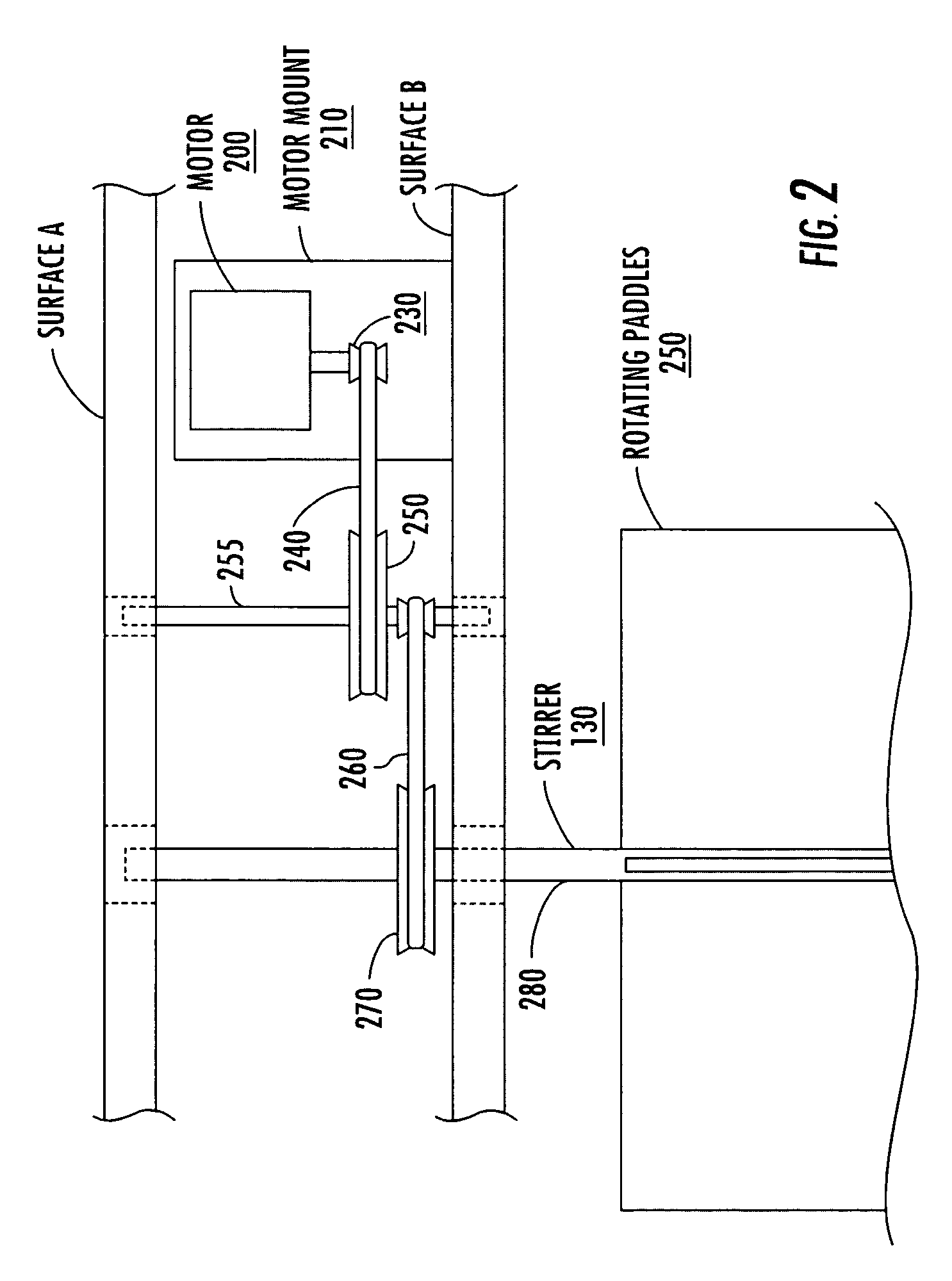
"The invention is about techniques that can test and evaluate materials in moving solutions. It uses a circular tank with rigid panels and a motor-driven stirrer to create a rotating liquid. This allows for the testing of materials without needing them to have a circular shape conforming to the tank's diameter. The technical effect is the ability to dynamically test and evaluate materials in moving solutions."

Problems solved by technology

None, however, offer an economic, efficient and well-calibrated system that enables hydrodynamic, physical and chemical conditions to be measured at the material surface.
The disadvantages, however, are many.
The design requires a large horsepower pump to achieve the high velocity of water flows due to inefficiencies caused by large pressure losses in the system.
The system is expensive to build.
The system is not suited to test a large number of samples as it can only accommodate one test panel at each velocity.
Large diameter drums are capable of testing several panels at a time, however, the panels are usually small and require a curvature to match the radius of the drum which make then unsuitable for subsequent hydrodynamic testing in water, tunnels or boats.
The systems require large horsepower motors and are energy inefficient due to losses to the surrounding water.
The flow characteristics, however, are complex and variable across the test surface and this makes it difficult to use the data to model for full-scale prediction performance.

Method used


Image

  • Techniques for dynamically testing and evaluating materials and coatings in moving solutions
  • Techniques for dynamically testing and evaluating materials and coatings in moving solutions
  • Techniques for dynamically testing and evaluating materials and coatings in moving solutions

Examples


Embodiment Construction

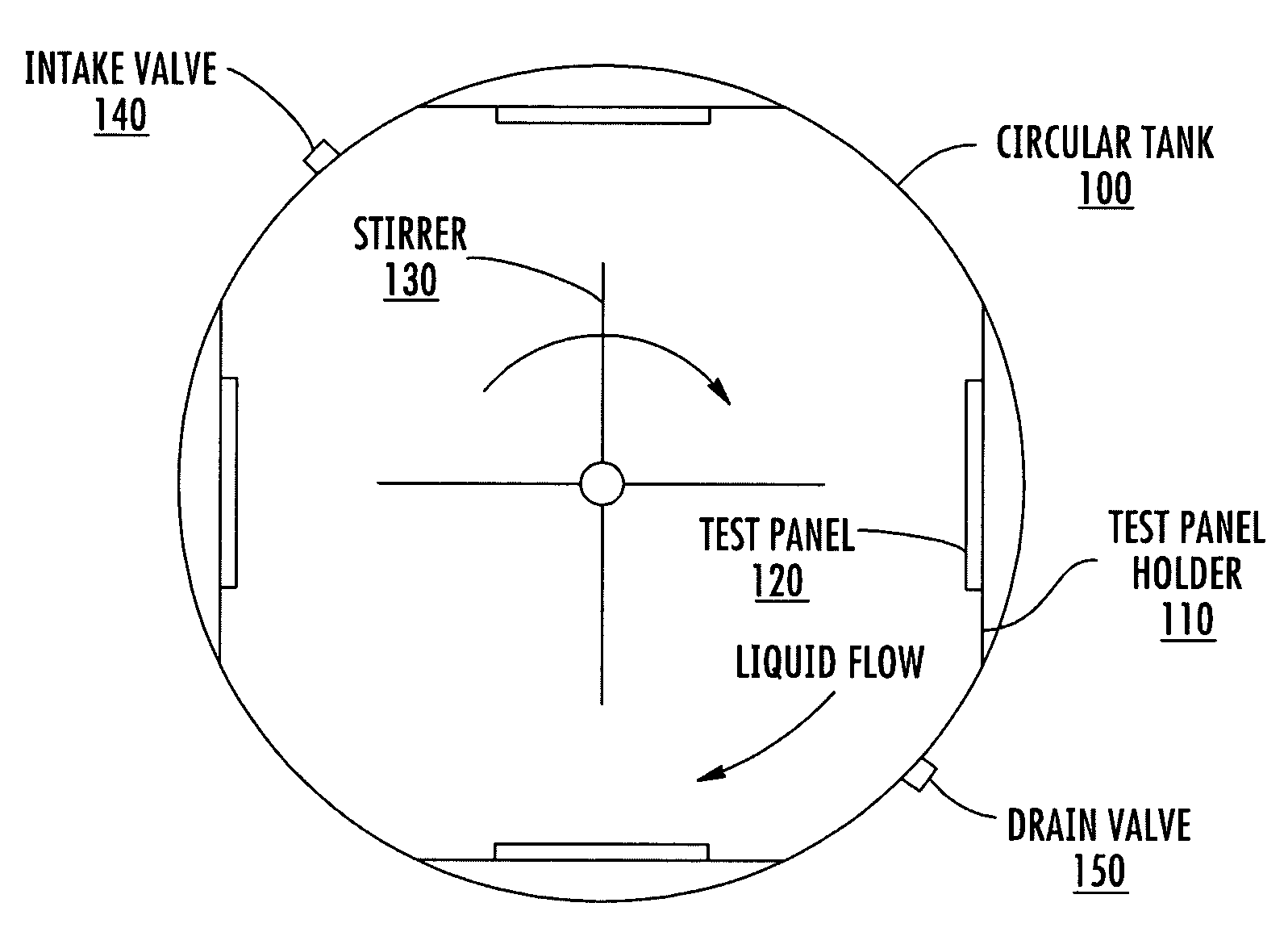
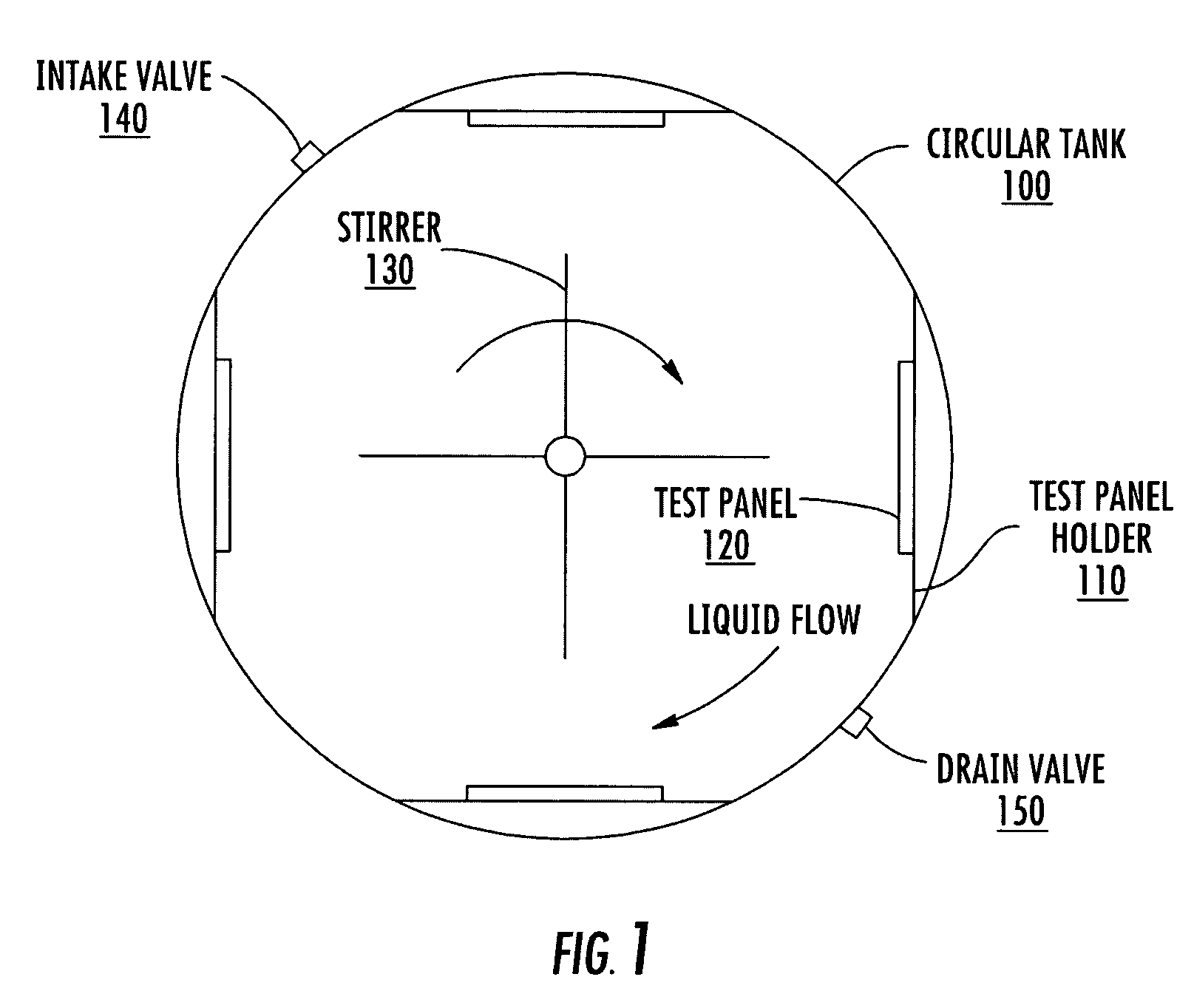
[0021]FIG. 1 is a top view of a test tank showing operational interactions in accordance with one aspect of the invention. In FIG. 1, a circular tank 100 is utilized to contain a test liquid, such as seawater. Seawater can be placed in the tank either from the open top or through optional intake valve 140 and may be drained from the tank either by siphoning out or through use of optional drain valve 150. In implementations where a continuous supply of fresh seawater is required, the intake valve may be opened to allow new seawater to be received and the drain valve may simultaneously open to allow an equivalent amount of seawater to drain from the tank. The water intake and outflow from the tank can be controlled automatically to maintain a given level of the fluid within the tank. One way of controlling the amount of seawater within the tank would utilize a float, connected to a switch, which would activate the drain valve 150 when water exceeded a certain level.

[0022]Attached to t...


PUM

PropertyMeasurementUnit
velocityaaaaaaaaaa
length of timeaaaaaaaaaa
shear stressesaaaaaaaaaa

Abstract

The dynamic testing of materials in moving solutions, such as anti-fouling paint in seawater, is conducted in a cylindrical tank. A stirrer having a drive shaft and one or more paddles or blades is driven by a variable speed motor to rotate and to impart rotational velocity to a liquid, which passes over the test materials which are attached to the periphery of the tank. The flow conditions over the surface can be well characterized. The surface of the test materials may be instrumented to measure physical, chemical and hydrodynamic conditions. The energy required for testing is reduced over prior art techniques.

Description

CROSS REFERENCE TO RELATED APPLICATIONS[0001]This application is related to U.S. provisional application 60 / 517,341, filed Nov. 5, 2003, by Geoffrey Swain and Arthur Touzot, the contents of which are hereby incorporated by reference in their entirety. In addition, this application claims priority to that provisional application.STATEMENT REGARDING FEDERALLY SPONSORED RESEARCH OR DEVELOPMENT[0002]The invention described herein was submitted as an expansion to office of Naval Research Contact N00014-02-1-0216, pursuant to its long range scientific and technology program BAA 03-001.BACKGROUND OF THE INVENTION[0003]1. Field of the Invention[0004]The invention is directed to techniques for testing and evaluating materials and coatings and, more particularly, to testing and evaluating materials and coatings in moving solutions.[0005]2. Description of Related Art[0006]The techniques of the invention as well as the techniques the prior art are intended to measure the performance of material...

Claims


Application Information

Patent Timeline
Patent Type & Authority Patents(United States)
IPC IPC(8): G01N17/00
CPCG01N17/002
Inventor SWAIN, GEOFFREYTOUZOT, ARTHUR
Owner FLORIDA INST OF TECH
Learn More