

Component mounting apparatus and component mounting method
a technology for mounting components and mounting devices, which is applied in the direction of metal working devices, instruments, manufacturing tools, etc., can solve the problems of shortening the development period, failing to improve processing speed, and inability to provide apparatuses that can cope with a variety of needs, so as to reduce the developmental period of control the effect of improving the controllability of the motion control of the constituent section
- Summary
- Abstract
- Description
- Claims
- Application Information
AI Technical Summary
Benefits of technology
Problems solved by technology
Method used
Image

Examples
first embodiment
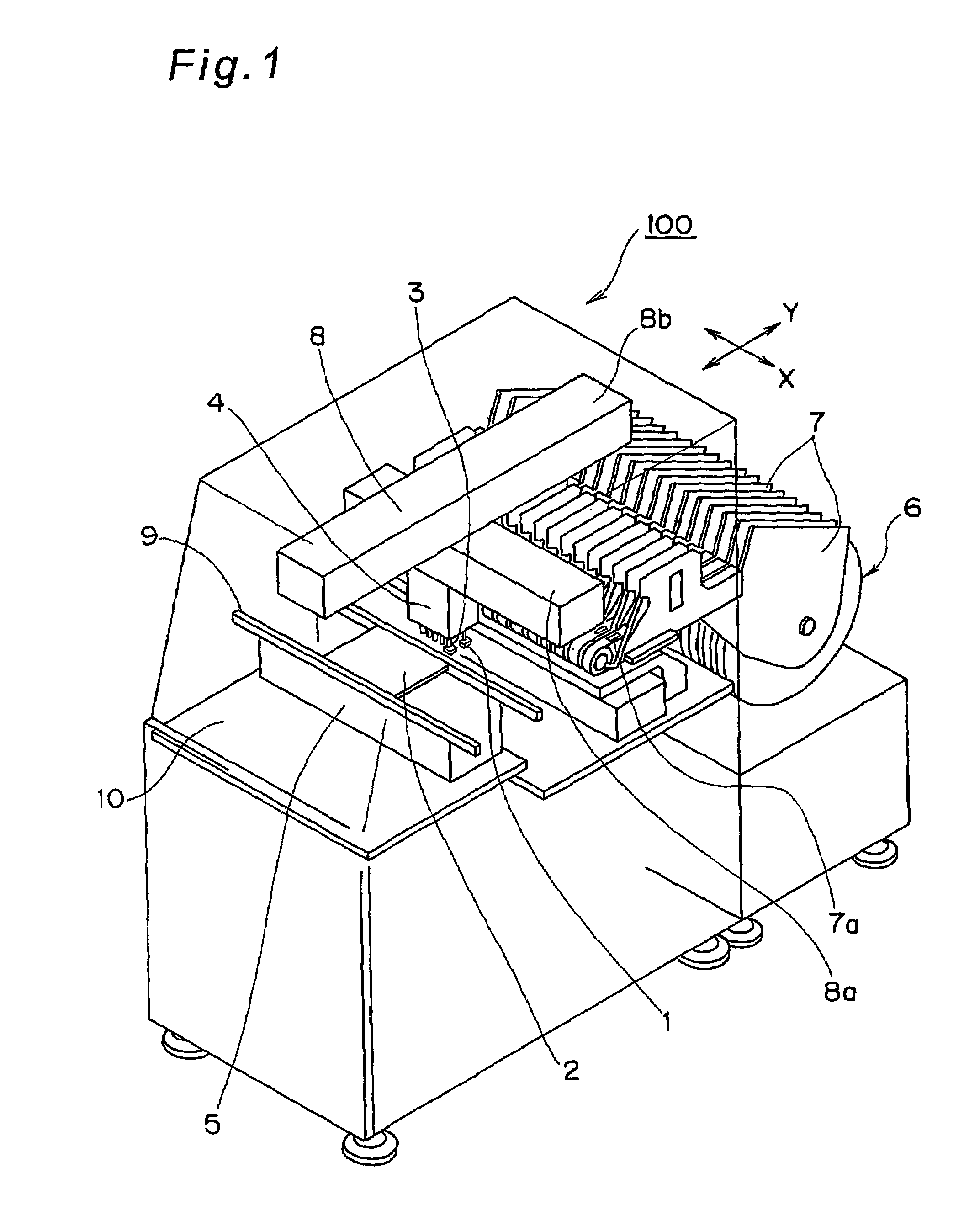
[0154]FIG. 1 shows a schematic explanatory view schematically showing construction of a component mounting apparatus 100 as one example of a component mounting apparatus according to a first embodiment of the present invention.
[0155](Overall Construction of the Component Mounting Apparatus)
[0156]As shown in FIG. 1, the component mounting apparatus 100 is provided with a component feed unit 6 as one example of a component feed unit for feeding a plurality of components 1 while allowing the components 1 to be picked up, a stage 5 as one example of a board holding section for releasably holding a board 2 onto which each of the components 1 to be fed is mounted, a head unit 4 that holds and picks up each of the components 1 fed from the component feed unit 6 while allowing each of the components to be picked up and executes mounting of each of these held components onto the board 2 held by the stage 5, and an X-Y robot 8 as one example of a head moving unit for executing a conveyance op...
second embodiment
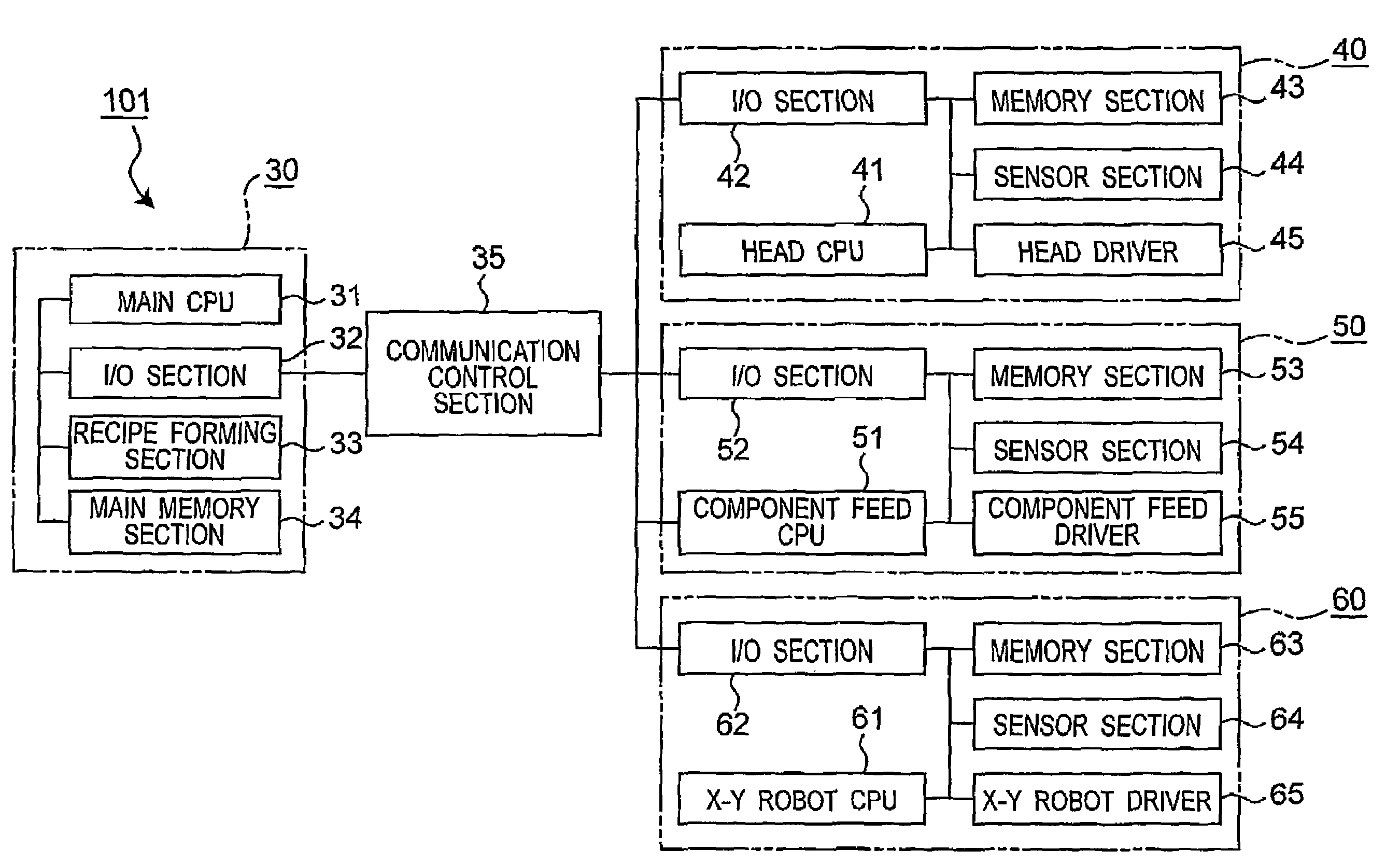
[0281]The present invention is not limited to the aforementioned embodiment and is able to be materialized in other various embodiments. For example, FIG. 15 shows a control block diagram showing a principal construction of a distributed control system 301 provided for a component mounting apparatus according to a second embodiment of the present invention.
[0282]As shown in FIG. 15, the distributed control system 301 has a construction differing from the distributed control system 101 of the first embodiment in that the X-Y robot distribution unit 60 is not provided, although this control system is provided with an MMC 330 that is one example of a main control section, a head distribution unit 40 that is one example of a head unit control section, a component feed distribution unit 50 that is one example of a component feed unit control section, and a communication control section 35 that is an interface board for controlling informational communications between the MMC 330 and the ...
third embodiment
[0285]Further, FIG. 16 shows a schematic perspective view showing a schematic construction of a component mounting apparatus 400 that is one example of a component mounting apparatus according to a third embodiment of the present invention.
[0286]As shown in FIG. 16, the component mounting apparatus 400 differs from the component mounting apparatus 100 of the first embodiment in that two head units and two X-Y robots are provided, and only different sections will be described below. In FIG. 16, sections that have the same constructions as those of the component mounting apparatus 100 are denoted by the same reference numerals.
[0287]As shown in FIG. 16, the component mounting apparatus 400 is provided with a component feed unit 6 that feeds a plurality of components 1 while allowing the components 1 to be picked up, and a stage 405 that is one example of a board holding section that releasably holds two boards 2a and 2b on which fed components 1 are mounted. The component mounting app...
PUM
| Property | Measurement | Unit |
|---|---|---|
| height | aaaaa | aaaaa |
| transmission section | aaaaa | aaaaa |
| transmission | aaaaa | aaaaa |
Abstract
Description
Claims
Application Information